Artillery Glossary
A-C Terms
AMMUNITION: Sometimes this name is given to cannon and mortars, as well as to the projectiles and explosive substances employed with them; but more usually ammunition is considered to apply to the latter – such as shot, shell gunpowder, cartridges, fuzes, wads, grenades. Muskets, swords, bayonets, and other small-arms are sometimes, but improperly, included under this term. The Royal Laboratory at Woolwich is the place where ammunition is chiefly prepared for the British army and navy. The cannon-balls may be cast at some of the great iron foundries in the North; the shells may be cast or forged in the shell-factory at Woolwich; the muskets may be made at Birmingham, and the rifles at Enfield; the bullets at the shot-factories; the gunpowder at Waltham Abbey – and so on; but the "making up" of the ammunition is mostly conducted at the establishment above mentioned. In the United States, ammunition is prepared at the various Arsenals and by numerous private Manufacturing Companies. Bags of serge, in enormous number are cut out and made, and filled to form the cartridges for large ordnance. Bags or tubes of paper are made and filled to constitute blank cartridges for small-arms; while the ball-cartridges are enclosed in thin copper cylinders. The tubes and combustibles for war-rockets and fuzes are also manufactured. The cartridges for small-arms (rifles, muskets, carbines, and pistols) are made in millions; since it is on those that the main offensive operations of an army depend. It has been calculated by the Woolwich authorities that a British army of 60,000 men, comprising a fair average of infantry, cavalry, artillery, and engineers, ought to be provided with no less than 18,000,000 ball-cartridges for small-arms, for six months’ operations. These would require 1000 ammunition-wagons and 3600 horses to convey them all at once. It is therefore deemed better that, under any such circumstances, there should be established entrepots for supplying the troops from time to time. The wagons constructed for this kind of service will carry 20,000 rounds of small-arm ammunition each; the cartridges are packed in boxes, and the wagons are drawn by four horses each. Several wagons are organized into an "equipment," under the charge of a detachment of artillery; and there are several such equipments for an army of the magnitude above mentioned – one for each division of infantry, a small portion for the cavalry, and the rest in reserve. It has been laid down that an army of 60,000 men ought to have 2,680,000 cartridges with them, besides those in reserve; and that the conveyance of such a quantity, with a few forges and stores, would require 150 ammunition-wagons, 830 men, and 704 horses. The equipment would return to the entrepot for a new supply when needed. In the Peninsular War, and at Waterloo, the English used two-horse carts, carrying about 10,000 rounds of small-arm ammunition each; but a superior kind of wagon has been since introduced. In the field, an infantry soldier usually carries about 60 rounds, put in compartments in his pouch. When the word ammunition is used in connection with artillery matters, the "fixed" ammunition comprises the loaded shells, cartridges, and carcasses; whereas the "unfixed" are the unfilled case-shot, grape-shot, and shell. Curing peace, the Woolwich laboratory serves out little less than 1,000,000 lbs. Of gunpowder annually, in ammunition for the army and navy, for the purposes of exercising, saluting, etc. The chief kinds of ammunition will be found briefly described under their proper headings. See Ammunition-boxes, Breaking up Ammunition, Cartridge, Center-fire Metallic-case Cartridge, Field and Mountain Ammunition, Fixed Ammunition, Metallic Ammunition for Small-arms, Paper Ammunition for Small-arms, Preservation of Ammunition and Fireworks, Siege and Garrison Ammunition, Stand of Ammunition, and Strapped Ammunition.
AMMUNITION-BOXES: Packing-boxes for field ammunition are made of well-seasoned stuff (generally white pine), 1.25 inch thick, dovetailed with the tenon on the ends. The top of the box is fastened with six 2-inch screws; the box has two handles of 1 ¾ inch rope, attached to brackets at the ends. The boxes are painted on the outside different colors to indicate the contents of the box. Those containing shot are painted olive; shells, black; spherical case-shot, red; and canisters, a light drab. The kind of ammunition is marked on each end in large white letters. The place and date of fabrication are marked on the inside of the cover. The boxes are packed as follows:
For Smooth-Bore Guns. – Shot, spherical case and canisters, fixed. – Laid in two tiers across the box, the shot or canisters alternating with the cartridges at each side. The shot or canisters of the upper tier rest on those of the lower and not on the cartridges. Canisters are packed in the same manner, omitting the strips of wood in the bottom of the box.
For 12-pounder Mountain-Howitzer. – Shells and case-shot, fixed. – Placed upright, the balls down, resting on strips of wood as for the other howitzer. Canisters are packed in the same manner, resting on the bottom of the box.
For Rifled Funs. – Shells and case-shot. – Placed upright, the balls down, resting on strips of wood as for the howitzer. The iron part of the balls rest against strips of wood 4 inches wide and .25 inch thick, nailed to the side and ends of the box at the bottom, and similar strips placed between the rows of the balls to prevent the soft metal cups from bearing against the box or against each other and being bruised; the cartridges are placed on top of the projectiles. Canisters are packed in the same manner as the case-shot, omitting the strips of wood on the bottom of the box.
In all the boxes the small stores are placed in the vacant spaces on top of the ammunition. A layer of tow is placed in the bottom of each box, and the whole contents are well packed in tow, filling the box so as to be pressed down by the cover. About three pounds of tow are required for a box. See Ammunition and Madigan Ammunition-box.
AMMUNITION CHEST(S): Wooden chests used to store ammunition for use in the field. When being transported, the chests were attached to the artillery limber and served as a seat for the cannoneers. Large metal handles on each end served to lift the chest and as a hand support for the cannoneers seated on the chest. The weight of an empty chest was 185 pounds, a fully-loaded chest could weigh as much as 560 pounds depending upon the type of ammunition. Limbers could hold one chest and caissons usually held two. Chests are placed on field-limbers and caissons for the transportation and safe-keeping of the ammunition. The limber has one and the caisson has three such chests, which will seat twelve cannoneers if necessary. The interior compartments of the ammunition-chests vary according to the nature of the ammunition with which they are loaded.
AMMUNITION CRATE: Also known as a packing box. Crates were made of wood with rope handles and were stenciled on the outside to indicate the contents. Those containing shot were painted olive; shell, black; spherical case-shot, red; and canister, a light drab. The kind of ammunition was marked on each end in large white letters. The place and date of manufacture were marked on the inside of the cover.
AMMUNITION-WAGON: A carriage employed for the transportation of ammunition. The points essential in the general construction of field-artillery carriages apply equally in that of the ammunition-wagon, so far as the traveling conditions are concerned. It need only be observed that the general form of a limber-carriage can be most effectively retained in the ammunition-wagon by substituting a perch for the trail of the gun-carriage, and furnishing it with an eye in front for an attachment to the limber-hook. The arrangement of the ammunition-boxes on the platform of the body must be such as to insure the center of gravity of the entire load falling between the wheels and limber-hook, the pressure on the latter being regulated with particular reference to stability and ease of draught.
ANGLE OF DEFENSE: The intersection of two fortified lines - a salient angle pointed to the front, while a re-entering angle pointed to the rear.
ANGLES OF FIRE: The placement of a battery, or battery assignment, dictated the angle of fire used to achieve objectives. Angles of fire included:
Direct - battery of guns placed parallel to the face of the enemy’s works, or their line of troops, so that the projectiles struck it perpendicular.Enfilade - battery of guns placed at right angles to the enemy’s works, or their line of troops, so that the projectiles fell in a parallel line to the works, striking a number of targets from one end of the line to the other.
Oblique - battery placed to form an angle with the front of the object to be struck.
Plunging - battery placed to fire projectiles from a higher position above the enemy’s works.
Reverse - battery placed to fire projectiles to strike the interior slope of the parapet at an angle greater than 30 degrees.
Ricochet - batteries fired at a slight elevation so that the shot bounced destructively from target to target along the enemy’s works or lines of troops.
Slant - battery placed so the shot struck the interior slope of the parapet, forming with it a horizontal angle, not greater than 30 degrees.
Vertical - batteries placed to fire a projectile at such an angle that it described a lofty curve through the air before it fell, such as the fire from a mortar battery.
ANVIL CAP: A flat piece of metal contained in a percussion fuze. Its purpose was to serve as a hard surface for the nipple to strike, thereby causing the spark necessary to detonate the powder in the chamber of the projectile.
APRON: A piece of sheet lead used to cover the vent of a cannon to protect against the elements. This was later replaced by the vent cover.
ARMOR-PIERCING PROJECTILES: Projectiles intended for practice at objects composed of wood, masonry, or earth are made of cast-iron; but since the introduction of iron for the defense of ships for fortifications, a material possessing greater hardness than ordinary cast-iron is required to overcome the resistance opposed by thick wrought-iron plates. Both elongated and spherical projectiles for use against armor should be of the hardest and toughest material possible. The power of a projectile to stand up to its work and deliver its full blow on the target depends on the shape as much as on the quality of the metal of which it is composed.
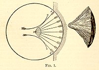 The
resistance of the plate, neglecting friction,
acts as a normal to each point of the surface of
contact of a spherical projectile; thus, in Fig.
1 it will be seen that the portion of such a
projectile included between A and B, which we may
term the zone of compression, is subject to a
crushing pressure towards the center, O, but it
may be said to be under no tensile strain. While
the posterior portion of the projectile is
suddenly checked by it in the form of a wedge,
when a portion of the work stored up inn it (the
amount depending on the tensile strength of the
material of the projectile) is impressed on the
target through the front portion, AOB, while the
remainder is carried off unprofitably in the
fragments into which the posterior portion
breaks. On examining the projectile after impact,
a part very nearly corresponding to AOB in form
will be found intact (Fig. 1) with the fractured
surface scored and polished, while the remainder
will be disperses in small fragments. We know
that any casting fractures most easily in the
direction of a normal to its surface, the
crystals settling themselves so as to form lines
on this direction. Theoretically, the portion
represented by Fig. 1 ought to be smaller as the
penetration is less – except in the case of
the entire blow being too small to overcome the
tensile strength of the metal in the manner
described: when the projectile would only split
irregularly, or, in an extreme case, remain
entire. In all instances obviously a great amount
of the work, stored up in the projectile is
wasted; not that actually employed in breaking
it, for such work is clearly the result of the
reaction from the target, but whatever power
remains stored up in the fragments after they
sever themselves from the mass of the projectile.
Since it is impossible to predict what part of a
spherical projectile fired from a smooth-bore gun
will come in contact with the target on impact,
it is necessary that the material should be such
as will offer the greatest union of hardness,
crushing strength, and tenacity; therefore steel
has been resorted to in some instances, and may
be regarded as the culminating point of
development of the smooth-bore projectiles.
The
resistance of the plate, neglecting friction,
acts as a normal to each point of the surface of
contact of a spherical projectile; thus, in Fig.
1 it will be seen that the portion of such a
projectile included between A and B, which we may
term the zone of compression, is subject to a
crushing pressure towards the center, O, but it
may be said to be under no tensile strain. While
the posterior portion of the projectile is
suddenly checked by it in the form of a wedge,
when a portion of the work stored up inn it (the
amount depending on the tensile strength of the
material of the projectile) is impressed on the
target through the front portion, AOB, while the
remainder is carried off unprofitably in the
fragments into which the posterior portion
breaks. On examining the projectile after impact,
a part very nearly corresponding to AOB in form
will be found intact (Fig. 1) with the fractured
surface scored and polished, while the remainder
will be disperses in small fragments. We know
that any casting fractures most easily in the
direction of a normal to its surface, the
crystals settling themselves so as to form lines
on this direction. Theoretically, the portion
represented by Fig. 1 ought to be smaller as the
penetration is less – except in the case of
the entire blow being too small to overcome the
tensile strength of the metal in the manner
described: when the projectile would only split
irregularly, or, in an extreme case, remain
entire. In all instances obviously a great amount
of the work, stored up in the projectile is
wasted; not that actually employed in breaking
it, for such work is clearly the result of the
reaction from the target, but whatever power
remains stored up in the fragments after they
sever themselves from the mass of the projectile.
Since it is impossible to predict what part of a
spherical projectile fired from a smooth-bore gun
will come in contact with the target on impact,
it is necessary that the material should be such
as will offer the greatest union of hardness,
crushing strength, and tenacity; therefore steel
has been resorted to in some instances, and may
be regarded as the culminating point of
development of the smooth-bore projectiles.
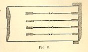 The
flat-ended form of elongated projectiles
possesses a peculiar advantage as regards the
projectile, and another as concerns the plate. As
to the projectiles, it may be seen (Fig. 2) that
in direct impact the whole of resistance of the
target acts in lines parallel to the
projectile’s axis, which direction is the
most favorable to the projectile retaining its
mass and delivering its full blow on the target;
and, again, if the target is to be punched by
actual shearing, the flat head is the form best
adapted to effect it. The flat head would
probably be best in the case of direct firing
against plates composed of hard iron, for it is
easy to conceive of a hard material offering very
great resistance to the forcing open of a pointed
head, which might be punched by the clean
shearing of a flat-headed projectile. The power
given by rotation of keeping the same portion of
a projectile presented to the front is of
peculiar value in punching armor-plates; it
enables the head of a projectile to be made of
any desired form, while the power of reducing the
caliber of a projectile in proportion to its
weight, which is perhaps the principal advantage
obtained by rifling, is also most important here,
the depth of penetration being in inverse
proportion to the circumference. In shells,
however, this stability of the axis of rotation
tells more fully, for it enables every part of
the projectile to be made of such proportions as
will give the maximum power at the moment of
impact. The walls of an elongated shell being
chiefly subjected to a longitudinal strain, an
interior hollow may be made without entailing the
great weakness existing in spherical shells as
compared with solid shot. Hence it follows that
while smooth-bore shells have seldom or never
been fired at armor, rifled shells have proved
very successful.
The
flat-ended form of elongated projectiles
possesses a peculiar advantage as regards the
projectile, and another as concerns the plate. As
to the projectiles, it may be seen (Fig. 2) that
in direct impact the whole of resistance of the
target acts in lines parallel to the
projectile’s axis, which direction is the
most favorable to the projectile retaining its
mass and delivering its full blow on the target;
and, again, if the target is to be punched by
actual shearing, the flat head is the form best
adapted to effect it. The flat head would
probably be best in the case of direct firing
against plates composed of hard iron, for it is
easy to conceive of a hard material offering very
great resistance to the forcing open of a pointed
head, which might be punched by the clean
shearing of a flat-headed projectile. The power
given by rotation of keeping the same portion of
a projectile presented to the front is of
peculiar value in punching armor-plates; it
enables the head of a projectile to be made of
any desired form, while the power of reducing the
caliber of a projectile in proportion to its
weight, which is perhaps the principal advantage
obtained by rifling, is also most important here,
the depth of penetration being in inverse
proportion to the circumference. In shells,
however, this stability of the axis of rotation
tells more fully, for it enables every part of
the projectile to be made of such proportions as
will give the maximum power at the moment of
impact. The walls of an elongated shell being
chiefly subjected to a longitudinal strain, an
interior hollow may be made without entailing the
great weakness existing in spherical shells as
compared with solid shot. Hence it follows that
while smooth-bore shells have seldom or never
been fired at armor, rifled shells have proved
very successful.
There are two causes which contribute to give shells peculiar power against iron plates. The first is that it is not necessary to weaken the head of a shell by making a fuze-hole in it; because no fuze is required, the heat generated on the impact of a projectile against the armor being sufficient to fire the bursting-charge. To such an extent is light as well as heat generated, that on firing oat a target after dark a pale flash is seen to follow the impact. The second cause that operates to favor the action of shells is the fact that when the shell has penetrated to a depth of even a few inches before rupture occurs, the sides are supported by the armor around them, and the explosion, being confined at the sides, acts to the front with greatly increased force.
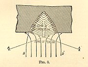
In a conical head the normal pressures throughout form a zone of compression acting as a wedge towards the body of the projectile, whose angle is the supplement of that of the cone of the head. This is better than that formed in the spherical head, because the angle is less acute, and because the apex of the wedge, instead of being a fixed point throughout (the center of the sphere), moves along the axis of the projectile as it enters deeper and deeper into the target. In the ogival head (Fig. 3) it will easily be seen how much superior is the action. In this the wedge is at the commencement slightly acute, but then the resistance acts on a small surface and is comparatively small, and the angle increases, till, at the junction of head and body, it becomes 180 degrees, or a straight line, so that we then have the body of the projectile in much the same condition as the flat headed bolt driving before it an ogival wedge, which opens the armor by wedging rather than by clipping or punching.
 It is
possible, no doubt, to conceive of a material
that might be sheared by the flat projectile more
easily than opened by the ogival; but it would be
to contradict the results of experience to say
that plate-iron was such a substance; and as the
softer and more plastic natures of plate-iron
have been found to hold their bolts the best, and
stand the longest, and so have been universally
adopted, the ogival has become obviously the
correct form of the head.
It is
possible, no doubt, to conceive of a material
that might be sheared by the flat projectile more
easily than opened by the ogival; but it would be
to contradict the results of experience to say
that plate-iron was such a substance; and as the
softer and more plastic natures of plate-iron
have been found to hold their bolts the best, and
stand the longest, and so have been universally
adopted, the ogival has become obviously the
correct form of the head.
The effect of hardening projectiles is
probably much greater than is generally supposed;
that is, the amount of work gained is much
greater than the increase of strength of the
projectile. It is well known that a very small
force may under certain circumstances determine
the performance or non-performance of a very
large amount of work. In like manner a very
slight addition to the rigidity of a projectile,
by hardening or otherwise, may determine
 whether a
very large amount of work shall be wasted upon
the projectile or expended upon the plate.
Another means of increasing the work done upon
the armor plate in comparison with that done upon
the projectile is by increasing the velocity of
the latter. That is, a projectile moving at a low
velocity may be smashed up or flattened against
the plate, while the same projectile fired at a
higher velocity may go through the same plate
almost uninjured. On this principle a lead shot
may be fired through an iron plate, or a tallow
candle through a pine board.
whether a
very large amount of work shall be wasted upon
the projectile or expended upon the plate.
Another means of increasing the work done upon
the armor plate in comparison with that done upon
the projectile is by increasing the velocity of
the latter. That is, a projectile moving at a low
velocity may be smashed up or flattened against
the plate, while the same projectile fired at a
higher velocity may go through the same plate
almost uninjured. On this principle a lead shot
may be fired through an iron plate, or a tallow
candle through a pine board.
Late trials have shown a superiority of steel projectiles over those made of chilled cast-iron; and although the former are somewhat more expensive than the latter, on the principle that the best is at the same time the cheapest, it would be misplaced economy to leave any means unavailed of to increase the penetrating power of projectiles. The quality of chilled projectiles, from the nature of their manufacture, is necessarily unreliable; whereas this is not the case with hammered cast-steel, or at least not to the same extent by far, even when large masses are produced; and the difficulty of manufacture increases with the caliber. The most essential difference in the behavior of steel and chilled projectiles on striking the target consists in the reaction on the projectile showing itself in the latter by breaking up, while the former are only set up. As the breaking up of the chilled shells may take place before the bursting-charge comes into operation, whereby the rending effect is considerably prejudiced, this material appears far less adapted for shells than steel. The superiority of steel in this respect is still further increased by the fact that the steel shell can have thinner walls, consequently a larger chamber, and can thus hold a larger bursting-charge than the chilled metal. – See Armor-plates and Projectiles.
ARMORER: One who was charged with the manufacture, repair, or preservation of weapons.
ARMORY: A manufactory or storage facility for arms and ordnance.
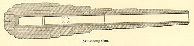
ARMSTRONG GUNS: The built-up gun construction of Great Britain, the germ of which is to be found in the coiled welded system of Sir William Armstrong, introduced to the artillery world in 1852 in the form of a breech-loading cannon, but passing from that date through numerous and important changes, especially the thickening of the coils and the introduction of tempered steel lining tubes, is the one which is still adhered to, in its general principles, by the ordnance constructors, both public and private, of the English nation. The failure of the Armstrong breech-loading guns, and the subsequent introduction of muzzle-loading cannon in lieu thereof, in 1869, did not change, however, one of the essential features of the present construction – the employment of coiled welded wrought-iron sections – but led to the modified form of their production known as the Fraser system, and the introduction of comparatively thin oil-tempered steel tubes for the interior lining. The most prominent guns produced under this new system, which first attracted universal attention on account of their great comparative power, were the 25-, 35-, and 38-ton guns; but these, as is well known, were quickly superseded by the 16-inch 80-ton gun, and it, in its turn, by the largest of, as yet constructed ordnance – the 100-ton guns of the Armstrong model, shown in section in the drawing.
The theoretical consideration that the ratio of the capacities for work of two tubes is only approximatively directly as their thicknesses, or, generally speaking, that a thin tube has more relative strength than a thick one to withstand interior bursting strains, is the essence of the theory of the built-up guns of the English model, and it is practically carried out in their present constructions; the inference to be drawn being that a homogeneous structure, having no subdivisions in its walls, does not bring into play the full strength of the entire thickness while under stress; and that guns constructed homogeneously, however thick, cannot long sustain pressures exceeding the tensile strength of the metal employed. Sanctioning the soundness of the theory that only by built-up constructions the most powerful and yet reliable guns can be produced, the next point for consideration is the arrangement of the different metals entering into the fabrication, so that the stronger metal (steel) shall form the walls surrounding the bore, and that the superimposed layers of wrought-iron shall be so placed on that each part, from the bore to the exterior, shall be, as far as possible, under strain in accordance with its capacity for work, considered in reference to tangential strains. The English authorities state: "This object we may obtain by employing a single metal for the several portions, and so disposing the various layers over each other that the inner layers or tubes are compressed by those outside them, while the exterior tubes are at the same time put into a state of tension, the inner layers being thus strengthened at the expense of the outer portions of the metal. In this case we obtain the whole strength of all the layers except a part of that of the outer and unsupported ring. It must not, however, be for one moment supposed that this theoretical perfection is ever reached; the nearest approach to it is far away from perfect, and theoretical advantages have to give way largely to practical considerations of manufacture. Again, we may arrive at a similar result by employing metals varying in elasticity or in tenacity for the several parts, those possessing the largest amount of strength constituting, of course, the inner portions, so that where the greatest stress is felt it will be borne by the stronger material. These two methods are sometimes called respectively those of initial tension and of varying elasticities. They may be, and frequently are, both employed in the manufacture of a gun, as in the case of the so-called Woolwich guns."
The longitudinal strain is provided for by the thick solid-bottomed steel tube, and the breech-plug screwed into the wrought-iron coiled tube, superimposing the inner tube, brings into play (in the latest model) the strength resulting from locking the tube and other parts together. The construction, briefly, we know is a steel tube, over which is shrunk coiled wrought-iron tubes; the majority of the larger calibers, except the 100-ton gun, having only two layers of wrought-iron tubes; the latter more perfectly brings into use the principles of initial tension, by having the wrought-iron casing subdivided into three instead of two parts. On theoretical considerations, the large number of coils employed in the original Armstrong construction enabled the designers more perfectly to carry out the idea of initial tensions by shrinkage; yet its expensiveness led to its abandonment, and the substitution of large and, in consequence, fewer coils; thus more imperfectly applying the principles which it was sought to follow as the true ones in making guns. Although economy, the object of the change, was attained, yet it is doubtful, from the large masses employed if the result is more than a very rough approximation to the asserted theories of construction. The broad differences in the physical properties of wrought-iron and steel, i.e., differences in elasticity and ductility and tensile strength, render problematical the perfect co-operation of the two metals, under repeated strains such as obtain in the use of guns; and it would seem that the more elastic and less extensible steel, in imparting its stress to the adjacent iron repeatedly, would enlarge the latter by degrees, so that eventually it would form but an imperfect support to the former, which would in that case more or less bear, in the system, the burden of the work in resisting tangential strains; and that its rupture under severer treatment would be finally the result. The manner in which this system in manufacture is practically carried out needs only, in view of the full description printed for public use, be but generally stated.
The tubes are generally of Firth’s production, and are furnished under contract to the Woolwich Arsenal. They are solid ingots which are first roughly bored and turned, and then tempered in rape-oil. The jackets or coils, shrunk over the steel tube, in the heaviest natures, range in number according to the length of the gun. Generally two layers of coils cover the breech part, all assembled in accordance with the principle of initial tension. The details of construction are fully given in English text-books, and need not be alluded to here. The 100-ton gun – the latest English muzzle-loading construction – generally speaking, differs from inferior calibers by the large number of shoulders provided on the steel tube, the latter being made in two parts, united together by a wrought-iron exterior band, and in the greater number of subdivisions of the jackets, or rather that the bands are relatively narrower than on other fabrications; besides, three layers obtain at breech, rendering it a more thoroughly built-up gun construction. Four of these guns – made by Sir William Armstrong & Co., Newcastle-on-Tyne – now form part of the armament of Great Britain and her Colonies, and now await their emplacements to be prepared for them at Malta and Gibraltar. We are informed that "guns have already been designed and could be readily made at Woolwich which would surpass the latter 100-ton gun’ in power to as great an extent as they themselves surpass the 38-ton service-gun."
The English Government establishment, however, has not produced any muzzle-loading constructions higher than the 80-ton gun, a gun, from the large facilities and perfected machinery of Woolwich, giving us the best exhibit of the Armstrong-Fraser system. That no recent attempts, however, to introduce higher natures of muzzle-loading guns have been made is fully justified by the important developments of Krupp’s experiments at Meppen in August, 1879, and by the disasters occurring on board the English iron-clad the "Thunderer" in the same year; the first calling attention to the presumed superiority of breech-loading guns – since accorded – in affording less exposure to men; reduced size of embrasures, securing greater rapidity of fire; increased length of bore, and hence greater power; and also affording greater facilities for bore examinations, and permitting an ease in loading not afforded in long-bored muzzle-loading guns; and the latter exhibiting the dangers arising from the possibilities of double charging, and the cumbersomeness and complica6tions of loading devices necessary for the use of muzzle-loading guns, more especially in the naval service, where economy of space is a matter of vital importance. Although the developments at Meppen and the Thunderer misfortune only occurred a few years ago, yet such was the moral effect that immediate steps were instituted to develop breech-loading guns of 12-inch caliber and lower natures.
The principal dimensions of the Woolwich and Elswick guns are as follows:
Woolwich |
Elswick |
|
| Total length of gun without carrier in. | 333 |
331 |
| Caliber in inches | 12 |
12 |
| Bore: | ||
| In calibers | 26 |
26 |
| In inches | 312 |
312.2 |
| Total capacity in cubic inches | 39,057 |
38,784 |
| Chamber: | ||
| Diameter in inches | 15.5 |
14.3 |
| Length in inches | 58.35 |
87.43 |
| Capacity | 10,120 |
13,178 |
| Diameter in rear opening in inches | ……………………….. |
12.4 |
| Rifling: | ||
| Twist in caliber | ||
| Length in inches | . |
220.36 |
| Number of grooves | 48 |
50 |
These constructions (of the same caliber, 12 inch) differ very little from each other in their main features, such as modes of construction, principal dimensions, breech fermeture, and length of bore, the only important variations being in the lengths and diameters of chambers and their capacities; the Elswick gun having a less diameter and a greater length for this part of the bore, and also a greater capacity than the Woolwich pattern; this latter feature increasing the air-space in the chamber of the former over the latter when equal charges are used. It also, for the same diameter of the exterior, gives a stronger gun (both using the same metals) in its walls. A tabulated statement of these points of difference may be here inserted:
| Powder-chamber. | Powder-chamber. |
| Elswick: | R. G. F.: |
| Length……………in. 86.25 | Length……………in. 58.35 |
| Diameter………… in. 14.3 | Diameter…….……." 15.5 |
| Capacity…....cubic in. 13,178 | Capacity…… cubic " 10,120 |
The Woolwich authorities have established 17.1 tons per square inch as the service-limit for pressure, yet Armstrong for his constructions reaches 25 tons per square inch, and in his 10.15-inch wire gun a pressure of 34 tons per square inch has obtained. Cast-iron alone, or cast-iron in combination with wrought, or with wrought-iron and steel, or with steel alone, in guns for, say, one caliber and a half thickness of walls, cannot endure the chambering and in consequence the increased charges, which constructions made of steel alone, or steel in combination with wrought-iron, can sustain; and hence any plain using the inferior metal looking to a rivalry with the superior modern constructions which ignore the use of cast-iron would be a risk too hazardous to assume, and when the pressures reach, in guns using cast-iron, a limit of, say, not exceeding 35,000 to 37,000 pounds for a gun one and one half calibers thick, the service-limit should be regarded as reached, and the charges and chambering should be so regulated as to keep within these limits, which should be established as the limits of safety.
In steel guns a little less than one caliber is regarded as sufficient thickness of walls; and a caliber and one quarter, about, is used over the chambers of the 43-ton guns composed of steel and wrought-iron. In steel-tubed guns, surrounded by a wire and a part steel and part wrought-iron jacket, the thickness of walls given over the chamber is but eighty-five one-hundredths of a caliber. These figures illustrate the vast difference in the eyes of European gun constructors between the use of pure steel and the combination of steel and wrought-iron, and more especially in any construction in which cast-iron plays a prominent part. It would seem, therefore, independent of the recognized fact of the inferiority of cast-iron in strength, that the important element of weight would become largely a factor for consideration in judging of constructions using this metal, either alone or in combination with others. In fact as much power can be secured from a 43-ton (12-inch) gun (steel and iron) as from a 12-inch 55- to 60-ton gun (built-up) of cast-iron and steel.
 In a 44-ton
(13-inch) wire gun we have the remarkable exhibit
of a yield of 27,460 foot-tons muzzle-energy, or
say, 637 foot-tons per ton of metal. The cat-iron
and steel constructions (60 tons) alluded to
above only give 359 foot-tons per ton of metal.
The 10.15-inch wire gun recently constructed has
been tested, and the distinction between it and
the last-mentioned gun is more pronounced in
favor of wire than the 13-inch; the resulting
muzzle-energy giving 760 foot-tons per ton of
metal. The pressures are relatively higher in
attaining these results, yet the strength of the
combination is believed to warrant a large
increase over the ordinary standard pressure
adopted for the guns of the English service.
Admitting that about 37,600 foot-tons
muzzle-energy can be attained with a 13-inch of a
weight of, say 44 tons (wire), we find that it
takes 50 per centum more weight (60 tons) in a
gun (12-inch) using cast-iron to attain a much
less muzzle-energy corresponding to the
difference in calibers. The force of this
testimony regarding weight is evidently, as far
as it goes, against the use of cast-iron; and
when we consider the question of its employment,
pure and simple, this objection of increased
weight necessary in the structure becomes a
subject of the first importance, and one alone
which at the threshold of the consideration of
problem of gun construction should lead us to
doubt if it should be employed at all if we
desire to attain a high standard in power and
endurance in our future heavy ordnance armaments.
In a 44-ton
(13-inch) wire gun we have the remarkable exhibit
of a yield of 27,460 foot-tons muzzle-energy, or
say, 637 foot-tons per ton of metal. The cat-iron
and steel constructions (60 tons) alluded to
above only give 359 foot-tons per ton of metal.
The 10.15-inch wire gun recently constructed has
been tested, and the distinction between it and
the last-mentioned gun is more pronounced in
favor of wire than the 13-inch; the resulting
muzzle-energy giving 760 foot-tons per ton of
metal. The pressures are relatively higher in
attaining these results, yet the strength of the
combination is believed to warrant a large
increase over the ordinary standard pressure
adopted for the guns of the English service.
Admitting that about 37,600 foot-tons
muzzle-energy can be attained with a 13-inch of a
weight of, say 44 tons (wire), we find that it
takes 50 per centum more weight (60 tons) in a
gun (12-inch) using cast-iron to attain a much
less muzzle-energy corresponding to the
difference in calibers. The force of this
testimony regarding weight is evidently, as far
as it goes, against the use of cast-iron; and
when we consider the question of its employment,
pure and simple, this objection of increased
weight necessary in the structure becomes a
subject of the first importance, and one alone
which at the threshold of the consideration of
problem of gun construction should lead us to
doubt if it should be employed at all if we
desire to attain a high standard in power and
endurance in our future heavy ordnance armaments.
Independent of strength and increased weight, cast-iron guns of heavy natures require a cumbersome and expensive plant, consisting of deep pits, large furnaces, powerful cranes, and heavy and powerful lathes, etc., whereas in the built-up steel, and steel and wrought-iron systems, also wire guns, the numerous parts which go to make up the whole can, from their comparative lightness, be handled in the different operations of construction with far greater ease and less expense than obtain in the production of homogeneous masses consisting of but one piece, as found in systems where cast-iron enters either solely or largely into the fabrications. On the score of economy, it may be doubtful if any material advantage results in the use of cast-iron. English models cost about 14 cents per pound. To gain equal powers we would require, according to the ideas of constructors in cast-iron, at least a 60-ton gun to perform the same work as a 43-ton gun of steel and wrought-iron. If we estimate cast-iron at 12 cents per pound, we have a cost of $16,128 for a pure cast-iron gun of 60 tons; and admitting 14 cents per pound for wrought-iron and steel, we have a cost for a 43-ton gun of $13,484.80. If a net profit of 25 per centum for manufacturers is added to this latter figure, which is government cost, we have even then a less expensive construction than pure cast-iron in that country. See Built-up Guns and Ordnance.
ARMSTRONG PROJECTILE: But one kind of projectile is used in the Armstrong breech-loading guns for the field-service, and this is so constructed as to act as a shot, shell, or case-shot, at pleasure. It consists, as shown in Fig. 1, of a very thin cast-iron shell, snugly inclosing forty-two segment-shaped pieces of cast-iron (B B), built up so as to form a cylindrical cavity in the center (D), which contains the bursting-charge and the concussion-fuze. The exterior of the shell is thinly coated with lead (C C), which is applied by placing the shell in a mold and pouring it in a melted state. The lead is also allowed to percolate among the segments, so as to fill up the interstices, the central cavity being kept open by the insertion of a steel core. In this state the projectile is so compact that it may be fired without injury; while its resistance to a bursting-charge is so small that less than one ounce of powder is required to burst it. When the projectile is to be fired as a shot, it requires no preparation; but the expediency of using it otherwise than as a shell is doubted.
To make it available as a shell, the bursting-tube, the concussion- and time-fuzes, are all to be inserted; the bursting-tube entering first, and the time-fuze being screwed in at the apex. If the time-fuze be correctly adjusted, the shell will burst when it reaches within a few yards of the object; or, failing in this it will burst by the concussion-fuze when it strikes the object or grazes the ground near it. If it be required to act as a canister-shot upon an enemy close to the gun, the regulation of the time-fuze must be turned to the zero of the scale, and then the shell will burst on leaving the gun. The explosion of one of these shells in a closed chamber, where the pieces could be collected, resulted in the following number of fragments; 106 pieces of cast-iron, 90 pieces of lead, and 12 pieces of fuze, etc. – making in all 217 pieces.
The Armstrong projectiles for the
muzzle-loading guns have rows of brass or copper
studs projecting from their sides to fit into the
grooves of the gun, which are constructed on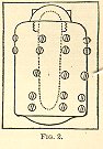 the shunt
principle. Fig. 2 represents a 10-inch Armstrong
Shell for penetrating armor-plates; It is made of
wrought-iron or low steel, with very thick sides.
There is no fuze, the explosion resulting from
the heat generated by the impact, and the
crushing in of the thin cap which closes the
mouth of the powder-chamber. The sides and bottom
of the shell being thick enough to resist
crushing by the impact, and also to resist the
explosive force of the bursting-charge, its
effect will, after penetration, be expended on
the backing of the armor, or the decks which the
armor is intended to screen. Such projectiles are
called "blind shells." See Projectiles.
the shunt
principle. Fig. 2 represents a 10-inch Armstrong
Shell for penetrating armor-plates; It is made of
wrought-iron or low steel, with very thick sides.
There is no fuze, the explosion resulting from
the heat generated by the impact, and the
crushing in of the thin cap which closes the
mouth of the powder-chamber. The sides and bottom
of the shell being thick enough to resist
crushing by the impact, and also to resist the
explosive force of the bursting-charge, its
effect will, after penetration, be expended on
the backing of the armor, or the decks which the
armor is intended to screen. Such projectiles are
called "blind shells." See Projectiles.
ARSENAL: A storage facility for ordnance and ordnance stores. Some arsenals were also used for the construction and repair of ordnance equipment.
ARTIFICER: Military workmen. Each artillery company was allowed two artificers.
ARTILLERIST: A soldier serving with the artillery.
ARTILLERY: 1) Generic term used to describe the heavy weapons of every description with the implements and materials necessary for their use. The weapons are broken down into four categories: Guns, Howitzers, Columbiads, and Mortars. These pieces are further categorized by their specific use: Seacoast, Siege and Garrison, and Field Artillery. Finally, artillery weapons may be denoted by type of bore (smooth or rifled). 2) Specific branch of the Confederate and Union armies and navies charged with the deployment, service, and maintenance of artillery. 3) Sub-units of the artillery branch, usually designated by state name, regiment number and/or name, battery letter, corps number, and specific army membership. Many of the sub units were also known by the name of their commanding officer or other non-standard references.
ARTILLERY CREW: Military personnel responsible for the maintenance, transportation, and operation of the various artillery pieces and the equipment and horses needed to properly support the battery. Each crew member working the cannon was assigned a number which dictated what his specific responsibility was during each phase of the operation of the guns. Support personnel included horse drivers, horse holders, and specialized functions such as blacksmiths. A Union army battery, at full strength, exceeded 100 officers and men.
ARTILLERY HORSES: See Horse Team.
ARTILLERY PARK: 1) A space occupied by animals, wagons, and artillery contiguous to a military camp. 2) A collection of one or more batteries.
ARTILLERY RESERVE: Designated batteries which were to remain limbered and hitched, ready to move quickly into position during battle. Their purpose was to replace disabled batteries or to move rapidly where the enemy was massing for an attack. The Army of the Potomac had a designated artillery reserve which practiced such maneuvers.
ARTILLERY SABER: A large, thick, curved blade having no basket guard often referred to as a saber.
ARTILLERY TRAIN: A military organization consisting of varying numbers of artillery weapons proportioned according to caliber and type. Siege weapons (guns, howitzers, mortars) were usually organized in trains of 100 pieces along with the required carriages, horses, ammunition, and gunpowder. Field trains were considerably smaller, usually consisting of three field weapons (guns and howitzers) per 1,000 infantry.
ASTRAGAL: Small convex molding used in the ornamental work of the cannon tube. It was usually connected with a fillet or flat molding.
AUGET: A groove on a traversing gun carriage which directed the recoil of a gun.
AXIS OF THE PIECE: The central line of the bore of an artillery tube.
BALLISTIC PENDULUM: An instrument which determined the force and velocity of a projectile during its flight.
BAR SHOT: Two hemispheres, or round shots, connected together by a short iron bar. When this shot was fired it began a rotation which, in theory, was supposed to cut the masts and rigging of naval vessels.
BARBETTE: Artillery elevated to fire above the crest of a parapet rather than through an embrasure. This was done by either raising the earth behind the parapet, or by placing the weapon on a high carriage. The advantage of barbette firing was a much wider range of fire unrestricted by the small embrasure.
BARBETTE CARRIAGE: An immovable wrought iron or heavy wooden carriage used for the mounting of garrison and seacoast artillery. Two varieties of the barbette carriage were the front-pintle (for the 8- and 10-inch Columbiad, and the 24-, 32-, and 42-pounder gun) and the center-pintle carriages (for the 8- and 10-inch Columbiad).
BARREL: See Tube.
BASE LINE: A line traced around the gun in the rear of the vent.
BASE RING: A projecting band of metal which adjoined the base of the breech, and was connected to the body of the gun by a concave molding.
BATTERIES: A battery consists of two or more pieces of artillery in the field. The term battery also implies the emplacement of ordnance destined to act offensively or defensively. It also refers to the company charged with a certain number of pieces of ordnance. The ordnance constitutes the battery. Men serve the battery. Horses drag it, and epaulments may shelter it. A battery may be with or without embrasures. In the latter case it is en barbette, and the height of the genouillere varies according to the description of the gun-carriage used. The ordnance constituting the battery requires substantial bearings either of solid ground for field-pieces, or of timber, plank, or masonry platforms, for heavy artillery. Batteries are sometimes designated as follows: Barbette battery, one without embrasures, in which the guns are raised to fire over the parapet; Ambulant battery, heavy guns mounted on traveling carriages, and moved as occasion may require, either to positions on a coast, or in besieged places; Covered battery, intended for a vertical fire, and concealed from the enemy; Breaking battery; Joint batteries, uniting their fire against any object; Counter battery, one battery opposed against another; Coast battery; Direct battery; Cross batteries, forming a cross fire on an object; Oblique battery, forming an angle of 20 degrees or more with the object against which it is directed, contradistinguished from direct battery; Raised battery, one whose terre-plein is elevated considerably above the ground; Sunken-battery, where the sole of the embrasures is on a level with the ground; and the platforms are consequently sunk below it; Enflading battery, when the shot or shell sweeps the whole length of a line of troops or part of a work; Horizontal battery, when the terre-plein is that of the natural level of the ground, consequently the parapet alone is raised and the ditch sunk; Open battery, without epaulment or other covering, wholly exposed; Indented battery, or battery a cremaillere, battery constructed with salient and re-entering angles for obtaining an oblique as well as a direct fire, and to afford shelter from the enfilade fire of the enemy; Reverse battery, that which fires upon the rear of a work or line of troops; Ricochet battery, whose projectiles, being fired at low angles, graze and bound without being buried; Masked battery, artificially concealed until required to open upon the enemy.
Field-batteries, in sieges, are usually of two kinds, viz., Elevated batteries and Sunken batteries, and they are placed either in front of the parallel, in the parallel itself, or in rear of it. In an elevated battery, the platforms for the guns or mortars to stand upon are laid on the natural level of the ground, and the whole of the covering mass, or parapet, is raised above that level, the earth for forming it being obtained from a ditch in front. In a sunken battery, the whole interior of the battery is excavated about three feet deep, and the platforms laid on the bottom, the earth is thrown to the front, and the parapet is formed out of it. Great care must be taken that no rise in the ground before the battery obscures the view from the soles of the embrasures; for this purpose, the officer laying out the battery should lie down and look along the ground, in order to be sure that his guns can range freely from their embrasures before he fixes his details for construction. When guns are fired with an elevation, when the soil is sandy or gravelly, when the weather is dry, or the ground elevated, this construction is approved. The depth of the excavation for the interior must depend on the height of the carriages upon which the guns are mounted: it should be deeper in rear than in front, that it may be drained. The interior slopes of these batteries, and the cheeks of the embrasures must be supported by field-revetments of gabions, fascines, sand-bags, casks, or sods. In batteries exposed to a heavy fire, especially of shells, it is necessary to provide as much cover as possible for the men serving in them; for this purpose, traverses are usually placed between every two guns; and as these masses serve to protect the men from the splinters of the bursting shells, they are generally called splinter-proof traverses. There is nearly twice as much work in the elevated as in the sunken battery.
A battery for four siege-pieces is represented in the drawing. In this construction, the parapet (A) is made of earth taken from the front, thus forming a ditch (C).
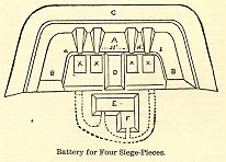 To protect
the pieces (XXXX) from flank fire, the parapet is
continued around on one or both ends, forming
epaulments (BB). The guns are in pairs, separated
by a traverse (D). The interval between the axes
of the embrasures of each pair is 16 feet for
guns on traveling carriages, and from 18 to 22
feet for sea-coast guns. Between the two middle
pieces this distance is increased by the
thickness of the traverse, generally about 15
feet. The entire length of the interior crest of
the parapet, from a to b, will therefore be 79
feet. This and other given dimensions are not
absolute, but indicate the method of obtaining
the data necessary for laying out any battery.
The length of the flank epaulments will depend
upon the direction of the enemy’s fire; in
all cases it must be sufficiently great to give
full protection to the whole interior from an
enfilading fire; generally it would be about 24
feet. The thickness of the parapet and epaulments
will depend upon the power of the artillery they
are expected to resist.
To protect
the pieces (XXXX) from flank fire, the parapet is
continued around on one or both ends, forming
epaulments (BB). The guns are in pairs, separated
by a traverse (D). The interval between the axes
of the embrasures of each pair is 16 feet for
guns on traveling carriages, and from 18 to 22
feet for sea-coast guns. Between the two middle
pieces this distance is increased by the
thickness of the traverse, generally about 15
feet. The entire length of the interior crest of
the parapet, from a to b, will therefore be 79
feet. This and other given dimensions are not
absolute, but indicate the method of obtaining
the data necessary for laying out any battery.
The length of the flank epaulments will depend
upon the direction of the enemy’s fire; in
all cases it must be sufficiently great to give
full protection to the whole interior from an
enfilading fire; generally it would be about 24
feet. The thickness of the parapet and epaulments
will depend upon the power of the artillery they
are expected to resist.
Batteries for even the heaviest pieces may be constructed on marshy ground by laying a grillage of timber over the surface and building up the parapet on it with sand-bags. To prevent the parapet from settling over towards the front, the grillage should extend several feet beyond it in that direction. In order that the platform of the piece may not be moved from its true horizontal position by any settling of the parapet, the space to be occupied by it is enclosed with strong sheeting piles. In this enclosed space several layers of fascines are laid, crossing each other at right angles; on these earth or sand is rammed, and the platform laid in the usual manner. If sand is used on top of the fascines, two or three thicknesses of paulins should be spread over them to hold the sand. Magazines in such localities must, of necessity, be entirely above ground, and supported on grillage in the same manner. See Embrasure.
BATTERING CHARGES: In the service of artillery there are two classes of cartridges, battering and full. The first is used with Palliser projectiles, and only under certain circumstances with common shell; the second is the ordinary charge used with common, double, shrapnel shell, and case-shot. The powder used would be pebble for all battering charges, and for full charges of 40 pounds and upwards.
The reason why pebble-powder is now used with all large guns instead of ordinary powder is explained as follows: That the pressure on the gun is much less, and the velocity greater, with the former than the latter. This increased velocity is due to the lower pressure of the powder, which is kept up longer in the bore than with quicker-burning powder, the velocity depending upon the pressure and the space over which it is exerted.
BATTERING PROJECTILES: Projectiles for battering purposes are made of cast-iron, chilled iron, and steel. Against parapets of earth common shell containing large bursting-charges are the most effective. Compound shot, having chilled cast-iron heads and cast-steel bodies, give good results, but they lack the power to carry their bursting-charge behind the armor which they can penetrate. The hardness and tenacity of steel shot and shell make them very effective against all kinds of armor. The great cost prevents their use when good results can be accomplished by chilled shot. Gunpowder is not a sufficiently powerful explosive for these strong shells, and, moreover, it explodes on impact. Satisfactory experiments have been made with bursting-charges of gun-cotton, which only explodes when the penetration is complete. Both forged and cast steel shells, well tempered, have perforated great thicknesses of wrought iron, in direct hitting, without being injured. Cast-steel projectiles, compressed by an hydraulic press while in a fluid state to drive out bubbles, give excellent results. In direct fire against steel-faced armor, cast-steel shells, owing to their great hardness, behave better than those of forged steel. The reverse is the case in oblique fire, where tenacity and toughness are the main considerations. All steel projectiles thus far tried break up against steel-faced armor in oblique fire. The longer the head of the projectile the greater the effect in direct fire, while for oblique fire the best effects are obtained with heads struck with a radius of two diameters. The flat-headed projectiles are much inferior to those with pointed heads in both direct and oblique fire. The respective advantages of light and heavy shells may be said to be as follows, assuming the powder-charge to be constant: The heavier shells, though starting with a lower initial velocity, keep up their velocity better than lighter ones, and so have a longer range of penetrative effect. The lighter shells have a higher velocity at short ranges, and a flatter trajectory; also, a greater number can be carried for a given weight. The projectile must no be so heavy as to strain the gun unduly, but this is easily avoided by the use of slow-burning powder and air-spacing. The cavity in shells should be as capacious as possible, so as to carry a large bursting-charge, but this will be controlled by the thickness which the head and walls must possess to give the necessary strength. See Armor-plates.
BATTERY: A term applied to one or more pieces of artillery, or to the place where they were positioned. In the Union army a battery was usually made up of six pieces of the same kind of cannon, while a battery in the Confederate army usually constituted four weapons. Batteries, under the command of a captain, were further broken down into sections. Each section consisted of two guns under the command of a lieutenant. One gun, along with a caisson and limber, was designated as a platoon and served under a sergeant and two corporals. A battery in the Union army could exceed 100 men and officers.
BATTERY ASSIGNMENT: Batteries were often assigned by how or where they were in position (served), or by a specified purpose in battle. The usual assignments were:
Ambulant - heavy weapons mounted on traveling carriages and moved, as circumstances required, to positions on a coast or to locations under siege.
Barbette - battery with no embrasures. Weapons were raised to fire over the parapet.
Breaching - sustained, directed fire against a specific target such as a fort wall. The purpose was to punch a hole through the target, thereby weakening or destroying it.
Coast - heavy weapons mounted permanently or semi-permanently for defense on the coast.
Counter - one battery opposed against another.
Covered - a battery intended for vertical fire and concealed from the enemy.
Cross - batteries which formed a cross fire on any object.
Defilade - batteries protected from a plunging fire directed from adjoining heights.
Direct - a battery ranged parallel to the face of the target so shot could strike perpendicularly.
Enfilading - shot or shell which swept the whole length of a line of troops or part of a work.
Horizontal - terreplein was that of the natural level of the ground, and the parapet alone was raised and the ditch sunk.
In Battery - siege battery with its guns run forward into embrasures, or a field battery with its guns unlimbered ready for action.
Indented - constructed with salient and re-entering angles for obtaining an oblique, as well as direct fire, and afforded shelter from the enfilade fire of the enemy.
Joint - batteries uniting fire against any object.
Masked - batteries artificially concealed until required to open upon the enemy.
Oblique - a battery which formed an angle of 20º or more with the object against which it was directed.
Open - a battery without epaulment or other covering, wholly exposed.
Plunging - shot fired from a position considerably higher than the target.
Raised - terreplein was elevated considerably above the ground.
Reverse - batteries which fired upon the rear of a work or line of troops.
Ricochet - batteries which fired projectiles at low angles. The projectiles grazed the ground or water and bounced without being buried.
Sunken - the base of the embrasure was on a level with the ground and the platforms were consequently sunk below it.
BATTERY-GUN: A gun having a capacity for firing a number of shots consecutively or simultaneously without stopping to reload. There are many varieties.
- A piece of ordnance having a number of load-chambers attached to a vertical axis, and consecutively presented at the rear of the cannon-bore. As each takes its place at the breach, it is advanced into the bore and locked before firing.
- A chambered breech-piece, revolving in a vertical plane, and presenting its chambers consecutively at the open rear of the barrel, which is common to all the chambers. The principle of construction is that of the revolving chambered pistol.
- A number of parallel barrels arranged in rank, and having connected vents for intercommunication of fire. The infernal-machine of Fieschi, which he fired on Louis Philippe, was a row of barrels clinched to a frame, and had a train of powder which was laid over all the vents in succession, like the row of barrels in a proving-house.
- The Requa battery consists of 25 rifles, each 24 inches long, mounted in a horizontal plane upon a field-carriage. It is breech-loading, the cartridges being forced into the chambers by a sliding-bar worked by two levers. By a lever beneath the frame the barrels may be diverged , so as to scatter the balls 120 yards in a distance of 1000 yards. The weight of the battery-gun used at Charleston, S. C., was 1382 pounds. Served by three men, it fired seven volleys, or 175 shots, per minute. Its effective range was 1300 yards.
- Forms of many-barreled cannon revolving on a vertical axis, the pieces being muzzle-loaded.
BATTERY WAGON: A two-wheeled cart used to carry the tools and supplies necessary to keep the leather, cloth, and wood equipment of the battery in good condition. It was linked to the limber to form a four-wheeled vehicle.
BATTLEMENT: A wall or parapet with indentations or notches.
BLAKELY GUN: The most approved pattern of the Blakely gun combines in its construction the principles of "initial tension" and "varying elasticity," the object of which is to bring the strength of all the metal of the piece into simultaneous play, to resist explosion.
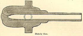 The drawing
shows the general features of the gun. The inner
tube, or barrel, is made of low steel, having
considerable but not quite enough elasticity. The
next tube is made of high steel with less
elasticity, and is shrunk on to the barrel with
just sufficient tension to compensate for the
insufficient difference of elasticity between the
two tubes. The outer cast-iron jacket, to which
the trunnions are attached, is the least elastic
of all, and is put on with only the shrinkage
attained by warming it over a fire. The steel
tubes are cast hollow and hammered over steel
mandrels, under steam-hammers: by this process
they are elongated about 130 per cent; at the
same time the tenacity of the metal is increased.
All the steel parts are annealed.
The drawing
shows the general features of the gun. The inner
tube, or barrel, is made of low steel, having
considerable but not quite enough elasticity. The
next tube is made of high steel with less
elasticity, and is shrunk on to the barrel with
just sufficient tension to compensate for the
insufficient difference of elasticity between the
two tubes. The outer cast-iron jacket, to which
the trunnions are attached, is the least elastic
of all, and is put on with only the shrinkage
attained by warming it over a fire. The steel
tubes are cast hollow and hammered over steel
mandrels, under steam-hammers: by this process
they are elongated about 130 per cent; at the
same time the tenacity of the metal is increased.
All the steel parts are annealed.
Captain Blakely uses other combinations of these metals, the simplest of which is a cast-iron gun with hoops of steel surrounding the reinforce. He objects to the use of wrought-iron on account of its tendency to stretch permanently. Blakely guns are rifled with one-sided grooves, and are fired with expanding projectiles. The following are the dimensions, etc., of Blakely all-steel guns:
Gun. |
Weight |
Diameter Of Bore. |
Length Of Bore. |
No. of Grooves. |
Twist. |
Weight of Projectile |
Weight of Powder |
Lbs. |
Inches |
Inches |
1 turn in Calibers. |
Lbs. |
Lbs. |
||
| 100-pdr | 8,000 | 6.4 | 96 | 8 | 48 | 100 | 10 |
| 120-pdr | 9,000 | 7 | 100 | 8 | 48 | 120 | 12 |
| 200-pdr | 17,000 | 8 | 44-156 | 12 | 48 | 200 | 20 |
| 250-pdr | 24,000 | 9 | Do. | 12 | 48 | 250 | 25 |
| 350-pdr | 30,000 | 10 | Do. | 15 | 48 | 350 | 35 |
| 350-pdr | 35,000 | 11 | Do. | 12 | 36 | 550 | 55 |
| 700-pdr | 40,000 | 12 | Do. | 12 | 36 | 700 | 70 |
See Ordnance.
BLAKELY PROJECTILE: This projectile has an expanding copper cup attached to its base by means of a single tap-bolt in the center, or other simple means. It is prevented from turning by radial grooves cast on the surface of the bottom of the projectile, into which the cup is pressed by the charge. The angle between the curved sides of the cup and the bottom of the projectile is filled with a lubricating material. On the forward part of the body are soft metal studs, more numerous than the grooves of the bore of the piece, that some of them may always form a bearing surface for the projectile against the lands. The driving sides of the grooves are deeper than the other. See Expanding Projectiles.
BLANK CARTRIDGE: A cartridge filled with powder, but having no projectile.
BLIND SHELL: A projectile with a hollow cavity which was plugged and not intended to have been fitted with a fuze. This projectile weighed less than a solid shot of the same caliber, which increased its velocity when it was fired. This shell which was similar to the cored-shot, also decreased the strain on the cannon.
BOAT GUN: Brass weapon designated by the Navy to be mounted on smaller boats for use on waterways and coastal areas. The primary guns were 12- and 24-pounder smoothbores and the 12-pounder rifled Dahlgren howitzer.
BOLSTER: A block of wood on the carriage of a siege gun. The breech rested on this when the piece was moved from place to place.
BOLT: An elongated projectile. See Solid Shot.
BOMB: A missile which also receives the names of bomb-shell and shell. It is a hollow ball, usually of cast-iron, fired from a mortar or other large piece of ordnance, and filled with combustibles which work great havoc when the ball bursts by the firing. All such projectiles were formerly fired from mortars only, and there was thus a definite relation between the bomb and the mortar; but since the invention of shell-guns and other modern pieces of artillery, the name shell has been generally substituted for that of bomb. The 13-inch bomb, which is the largest size used in ordinary warfare, weighs about 195 lbs., with a thickness of metal varying from 1 ½ to 2 inches at different parts; it bursts with about 8 lbs. of powder. The vent through which it is filled with powder is, after the filling, closed with a plug called a fuze, which sets fire to the powder, and at the proper moment bursts the bomb into fragments. The 10-inch bomb, weighing about 90 lbs., is proportionally less in all dimensions than that just described; and so on for those of smaller diameters. It should be understood, however, that the above are conventional quantities prescribed and adopted more than half a century ago. Modern artillerists try experiments on bombs of various degrees of thickness with various charges and fuzes. See Shell.
BOMB CHEST: A chest of powder placed underground which caused destruction when exploded by a fuze.
BOMB-KETCH: Also known as Bomb-Vessel. A small naval vessel strongly constructed to serve as a floating platform that supported the weight of and firing of a mortar or to transport mortars.
BOMB-PROOF: A term applied to military
structures of such immense thickness and strength
that bombs cannot penetrate them. Military
buildings generally within permanent
fortifications, and which are formed so as to
withstand the shock of heavy
 shot or
shell falling on them. Magazines for holding
gunpowder should be placed in the most sheltered
position within a fortress, and strongly
constructed to resist direct and vertical fire
from heavy ordnance. In the forts recently built
for coast-defense in England, 17 feet of masonry
as been considered necessary against direct fire,
and an arch 3 feet thick, with 3 feet of concrete
over the roof, against vertical fire.
shot or
shell falling on them. Magazines for holding
gunpowder should be placed in the most sheltered
position within a fortress, and strongly
constructed to resist direct and vertical fire
from heavy ordnance. In the forts recently built
for coast-defense in England, 17 feet of masonry
as been considered necessary against direct fire,
and an arch 3 feet thick, with 3 feet of concrete
over the roof, against vertical fire.
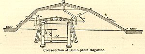
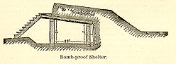
BOMB-PROOF MAGAZINE: For field-works of a semi-permanent character which are to be indefinitely occupied, have an armament of heavy guns, and are expected to stand a siege, - like the defenses around Washington, for example, - the magazines, bomb- and splinter-proof shelters should be constructed of the heaviest timber, and be covered securely with earth from the assailant’s curvated and direct fire. The ventilation of the magazines and precautions for their drainage are of the utmost importance. The drawing shows a cross-section of a magazine constructed in a work of this character. The sides of the interior of the magazine are formed of twelve-inch logs placed vertically in juxtaposition and resting upon a ground-sill. These are capped on top by a two-inch board, a strip of a like kind being spiked on within the cap. The top is formed of fifteen-inch logs, also in juxtaposition, each having a shoulder of three inches to fit it to the cap and inside strip. Longitudinal logs are laid on these with varying diameters, so as to give a proper pitch for the roof. Earth is solidly packed upon the top and between the roof-logs, receiving the proper slope for the roofing-boards. These boards, carefully jointed, are laid on in two thicknesses, each being covered with a coating of asphalt. The flooring of the magazine is of joists and boards. The sides of the magazine are surrounded with an air-chamber formed by inclined logs supported on a ground-sill and resting against the top logs; these are placed at three or four feet apart, each one being braced at the middle point to resist flexure from the pressure of earth. The chamber is covered in by saplings laid in juxtaposition. There are ventilators between the magazine and the air-chamber near the top, and also between the latter and the external air; the two not being opposite, and the usual precautions to guard against accident from sparks being taken. The earth-cover is ten feet on the exposed side, and six feet on the other sides and on top. The entrance to the magazine is well secured by a bomb-proof covering. A slope is given from the interior to the foot of the steps leading to the level of the floor for the purposes of draining.
BOMB-PROOF QUARTERS: Casemated bomb-proof
quarters are indispensable to the safety and
comfort of the garrison during siege, or any
prolonged attack for the annoyance of reduction
of the work by a bombardment. In small works like
most of our forts, which are chiefly designed for
sea-coast defense, casemated quarters have been
generally arranged in the rear of the batteries a
 portion of
each casemate towards the parade being
partitioned off and suitably disposed for the
object in view. In some cases advantage is taken
of a scarp-wall, on a land-front, which is well
covered by a glacis or other face-cover, to form
in its rear quarters of this character. In all
cases care should be taken to place such quarters
on those fronts which are best covered from a
direct fire, and the parade-walls of which are
not exposed to reverse-fire. Whenever the plan of
the work admits of it, quarters of this kind
should be arranged for defense, by being pierced
with loop-holes and even with embrasures for
cannon. Defensive casemated quarters form a
prominent and distinctive feature in what is now
known as the German School of Permanent
Fortification.
portion of
each casemate towards the parade being
partitioned off and suitably disposed for the
object in view. In some cases advantage is taken
of a scarp-wall, on a land-front, which is well
covered by a glacis or other face-cover, to form
in its rear quarters of this character. In all
cases care should be taken to place such quarters
on those fronts which are best covered from a
direct fire, and the parade-walls of which are
not exposed to reverse-fire. Whenever the plan of
the work admits of it, quarters of this kind
should be arranged for defense, by being pierced
with loop-holes and even with embrasures for
cannon. Defensive casemated quarters form a
prominent and distinctive feature in what is now
known as the German School of Permanent
Fortification.
BOMB-PROOF SHELTERS: These structures are for the protection of the troops when not on duty. They should be located on the parade, convenient to the pieces to be served, yet not so near as to interfere with the defense. They are usually constructed in half-excavation of logs built up like a log-house, or of a framework in the manner shown in the drawing, the exterior side being of heavy logs placed vertically in juxtaposition, resting on a ground-sill and capped at top. Parallel to this is another row, forming the other side, which may also be placed side by side or at short intervals apart, and capped like the outside row. The roof, consisting of heavy logs laid in juxtaposition and covered with thick boards joined, rests on the capping, the whole covered over on the side of the enemy with earth to a depth of at least 14 feet from the wood-work. To prevent this mass of earth from pushing the structure over to the rear, one in every two or three of the roof-logs is cut of sufficient length to extend about 8 feet beyond the front of the wall, and dovetailed to a longitudinal log help in position by vertical posts, the anchor-log being sufficiently covered with earth to protect it from injury by shot from the enemy. These bomb-proofs are made to serve the purpose of traverses, and are frequently arranged with a staging or gallery along the rear side for the accommodation of infantry, who deliver their fire over the top, arranged for this as a parapet. In all interior arrangements, system and regularity should be observed from the first; otherwise the work will grow into a labyrinth of confusion greatly opposed to efficiency and comfort. See Shelters and Splinter-proof Shelters.
BOMBARD: An ancient piece of ordnance, which
was very short, thick, and wide in the bore. It
differed from the balista in being worked with
gun-powder instead of by mechanical force, and
from the mortar in shooting forth stones instead
of iron shells. Some of the bombards used in the
fifteenth century propelled stones weighing from
200 to 500 pounds each. The shape of the first
cannon used after the invention of gunpowder was
conical, internally and externally resembling an
apothecary’s mortar. They were called
mortars, bombards, and vases; were fired at high
angles; and in consequence of the slow burning of
the powder of that day and the conical shape of
the bore, the stone balls projected by them
proceeded with very little velocity and accuracy.
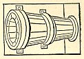 Bombards were made first of wood banded with
wrought-iron, then of sheet-iron strengthened by
hoops and brazing, and later of longitudinal iron
bars, connected and hooped, like the staves of a
cask. As none of these constructions gave the
requisite strength, cannon were subsequently made
of wrought-iron, then of cast-iron, and finally
of bronze.
Bombards were made first of wood banded with
wrought-iron, then of sheet-iron strengthened by
hoops and brazing, and later of longitudinal iron
bars, connected and hooped, like the staves of a
cask. As none of these constructions gave the
requisite strength, cannon were subsequently made
of wrought-iron, then of cast-iron, and finally
of bronze.
BOMBARDIER: An artilleryman versed in that department of arms which relates especially to bombs and shells, mortars and howitzers, grenades and fuzes. He has learned to load shells and grenades, fix fuzes, prepare composition for fuzes and tubes, etc.; and on the field or at sieges he fires the mortars. In some foreign armies the bombardiers form a separate corps; but usually there are some attached to every battery.
BOMBARDMENT: A showering of shells, red-hot shots, carcasses, rockets, or other incendiary projectiles, into a fortress or fortified city with the purpose being to burn and destroy the buildings and injure or kill people. Military engineers regarded bombardments against civilian cities as a cruel operation, but it was used to force a surrender or retreat of the occupying army in that area. Bombardments were used during siege operations against the cities of Atlanta, Vicksburg, Petersburg, and Richmond. An attack upon a fortress or fortified town by means of shells, red-hot shot, carcasses, rockets, etc., to burn and destroy the buildings and kill the people. A bombardment is most likely to be successful when the place is destitute of bomb-proof cover; or when the Governor is too humane to expose the unoffending inhabitants to this dreadful ordeal; or when the population is strong enough to compel him to yield. A bombardment requires little engineering science; whereas to reduce a place by regular siege requires the aid of engineers to direct the attack against fortifications, guns, and soldiery, leaving the inhabitants and buildings untouched. Military engineers generally regard a bombardment as a cruel operation; it is especially directed against the civilians and their buildings, as a means of inducing or compelling the Governor to surrender the place and terminate their miseries. In a well-defended place, the soldiers, the ammunition, and the defense-works suffer comparatively little, seeing that the bombardiers aim at pitching their terrible missiles into the heart of the place. In modern times a bombardment is mostly adopted as an adjunct to a siege, distracting the Governor by an incessant fire of mortars day and night. At Sebastopol, for instance, the mortars fired shells into the center of the city, to weaken the defense of the forts which were cannonaded by the siege-guns. Bombardment is more frequently a naval than a military operation. The stores required for a vigorous bombardment are immense. Thus, in 1759 Rodney threw 20,000 shells and carcasses into Havre; in 1792 the Duke of Saxe-Teschen threw 36,000 shot and shell into Lille in 140 hours; in 1795 Pichegru threw 8000 shells into Manheim in 16 hours; and in 1807 the English threw 11,000 shot and shell into Copenhagen in three days.
BONNET: A part of the parapet elevated to secure the terreplein from enfilade fire.
BORE: Includes all the drilled out portion of the tube including the chamber (if there is one), the cylinder, and the conical or spherical surface connecting them with the drilled out section.
BORE DIAMETER: The cannon diameter at its muzzle measured from wall to wall in a smoothbore, and from land to land in a rifled tube.
BORE LENGTH: The entire length measurement inside the tube including the chamber, if one was present.
BORMANN FUZE: This fuze is the invention of an officer of the Belgian service. The case is made of an alloy of tin and lead, cast in iron molds. It’s shape is that of a thick circular disk; and a screw-thread is cut upon its edge, by which it is fastened into the fuze-hole of the projectile. The upper surface is marked with two recesses and a graduated are. The former are made to receive the prongs of a screw-driver; and the latter overlies a circular groove, filled with mealed powder, tightly pressed in and covered with a metal cap. The only outlet to the groove containing the mealed powder is under the zero of the graduation; this outlet, or channel, is filled with rifle-powder, and leads down to a circular recess which is filled with musket-powder and covered with a perforated disk of tin. To enable this fuze to resist the shock of discharge, and at the same time to increase the effect of a small bursting-charge, the lower portion of the fuze-hole is closed with a perforated disk.
Before the projectile is inserted into the piece, a cut is made across the graduated portion, laying bare a small proportion of the mealed powder, which, being ignited by the flame of the charge, burns in both directions until the outlet is reached and the grain-powder ignited. The graduations are seconds and quarter-seconds, and the time of burning of the fuze depends on the length of the column of mealed powder included between the incision and outlet. If the metal covering be not cut, the projectile may be fired as a solid shot. The Bormann fuze is used for the field and siege services, and is found to be accurate and reliable, especially for spherical-case shot. The time of burning not being long enough for the general service of rifle-projectiles, the paper time-fuze is used instead of it for all of those projectiles which require the time-fuze. It is inserted into a zinc plug, which is screwed into the fuze-hole of the projectile.
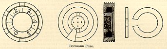 The action of
the Bormann fuze is as follows: The thin covering
of metal above the composition is cut so as to
lay bare the upper surface of the composition,
and to afford the flame access to it at the part
desired. The cut should be made with the
fuze-cutter close to the right of the mark in the
index-plate; and it is best made in two or three
efforts instead of trying to effect the cut at
once. The combustion occupies the assigned time
in passing from the incision towards the origin
of the graduation, when it traverses the orifice
leading into the magazine, the contents of which
explode smartly towards the interior, and then
encounter instantly the charge in the shell. The
metal of this fuze being soft and its diameter
great, there is danger of its screw-thread being
stripped, and its being driven in by the shock of
firing, or of its being driven out of the
ignition of the bursting-charge, thus affording a
means of escape for the gas evolved, without
bursting the shell. To prevent the former, a
broad shoulder, aa, is left when the fuze-hole is
tapped. To avoid the possibility of the latter
and at the same time to increase the effect of a
small bursting-charge, the fuze-hole below the
shoulder is closed by screwing in a composition
disk, b, with a small hole in its center through
which the fire from the fuze is communicated to
the charge.
The action of
the Bormann fuze is as follows: The thin covering
of metal above the composition is cut so as to
lay bare the upper surface of the composition,
and to afford the flame access to it at the part
desired. The cut should be made with the
fuze-cutter close to the right of the mark in the
index-plate; and it is best made in two or three
efforts instead of trying to effect the cut at
once. The combustion occupies the assigned time
in passing from the incision towards the origin
of the graduation, when it traverses the orifice
leading into the magazine, the contents of which
explode smartly towards the interior, and then
encounter instantly the charge in the shell. The
metal of this fuze being soft and its diameter
great, there is danger of its screw-thread being
stripped, and its being driven in by the shock of
firing, or of its being driven out of the
ignition of the bursting-charge, thus affording a
means of escape for the gas evolved, without
bursting the shell. To prevent the former, a
broad shoulder, aa, is left when the fuze-hole is
tapped. To avoid the possibility of the latter
and at the same time to increase the effect of a
small bursting-charge, the fuze-hole below the
shoulder is closed by screwing in a composition
disk, b, with a small hole in its center through
which the fire from the fuze is communicated to
the charge.
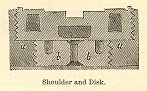 The
peculiar excellence of this fuze consists in the
driving of the whole mass of the composition by a
single pressure, and its disposition in such wise
that the combustion occurs not with the
stratification of the mass, but transversely to
it, while in the ordinary fuzes the
solidification and the process of combustion are
just the reverse; that is, the column is composed
of a number of layers solidified successively by
an equal pressure; but as the inferior layers
have, besides the pressure applied to them, to
bear that of the superincumbent layers, it
follows that the mass is not homogeneous, but
increases in density with the inferior position
of the layers. Click
here to see photographs of Bormann fuzes. See Fuzes and Time-fuze.
The
peculiar excellence of this fuze consists in the
driving of the whole mass of the composition by a
single pressure, and its disposition in such wise
that the combustion occurs not with the
stratification of the mass, but transversely to
it, while in the ordinary fuzes the
solidification and the process of combustion are
just the reverse; that is, the column is composed
of a number of layers solidified successively by
an equal pressure; but as the inferior layers
have, besides the pressure applied to them, to
bear that of the superincumbent layers, it
follows that the mass is not homogeneous, but
increases in density with the inferior position
of the layers. Click
here to see photographs of Bormann fuzes. See Fuzes and Time-fuze.
BOTTOM OF BORE: That portion of the bore which formed a plane perpendicular to the axis of the piece. It was extremely important to sponge this area thoroughly as it often contained sparks from incomplete burning of the powder bag.
BOURRELET: The raised rings on a rifled projectile larger in diameter than the projectile body. These rings helped center the projectile in the bore and were turned on a lathe to the dimension needed. Two bourrelets were the most common pattern and most often found on Confederate projectiles. Also referred to as a bearing surface.
BOW-CHASER: Also known as the bow-piece. A gun placed in the bow of a vessel.
BRASS: An alloy composed of copper and zinc and not suitable for ordnance. During the Civil War the term "brass" was often inaccurately used when describing bronze.
BREACH: An opening or rupture made in the wall of a fortification usually caused by the use of sustained shots fired against a pre-determined section. The most common way to cause a breach was to fire projectiles along a line and close together. Once the holes were made, the section was then heavily shelled until the breach was complete. Breaches were made to allow projectiles to reach vulnerable parts of a fort or to facilitate the passage of charging infantry.
BREASTWORK: A breastwork was a hastily constructed parapet, usually made of earth and wood, designed to protect the defenders against artillery and musketry fire. Also known as an entrenchment or field trench. Breastworks were normally constructed by the engineers, but in case of rapid troop movements the individual soldier was responsible for digging the emplacement. Breastworks usually contained a parapet, a revetment, and a banquette. In many cases the front of the work was protected by a deep ditch (from which earth was excavated to construct the parapet) or other obstructions such as abatis or chevaux-de-frize. The Civil War was the first conflict to make extensive use of trench warfare.
BREECH: The mass of solid metal behind the bottom of the bore of a gun which extended to the rear of the base ring.
BREECH BASE: A spherical segment forming the rear surface of the breech.
BREECH-LOADER: A type of weapon loaded through the breech rather than the muzzle. The rifled cannon had a screw assembly at the breech which could be opened for loading and then secured closed for firing. A few breech-loader cannons were introduced during the Civil War, but most were not successful in testing. The Whitworth and Armstrong cannons were notable exceptions.
BREECH PIN: A strong iron plug screwed into the breech end of a gun.
BREECH SIGHT: An upright sheet of brass which had a graduated scale of tangents and a movable slide that could be tightened down at any location on the scale. It was attached to a circular band which rested on the breech. When aiming the weapon, the gunner placed the sight on the breech and lined up the front sight with the slide. The range was then calculated and the gun elevated to the appropriate degree reading.
BREECHING: 1. The breeching of a gun or carronade is a strong rope by which the recoil of the gun is checked at such a point that the muzzle is brought wholly within the port-hole, where the sea-men can sponge and reload it. 2. Harness adapted to the wheel-horses of gun-carriages, near and off, for the purpose of facilitating the stopping of a gun in motion. Breechings, near and off, are strengthened with a lay of leather.
BRICOLE: See Men’s Harness.
BRITTEN GUN: This gun has five shallow grooves, and the projectile is expanding, being made of iron, but having a lead envelope, and a wooden sabot. The shell loads easily, being less in diameter than the bore; but when the gun is fired, the gas drives the sabot against the envelope and expands the lead into the grooves, so that the shot acquires a rotatory motion. The wooden sabot is now replaced by an iron shoe-piece, which is soldered to the soft-metal envelope; it is not liable, like the sabot, to partial separation, and serves to protect the soft metal.
BRITTEN PROJECTILE: The most novel and valuable part of this projectile is the fastening of a lead ring to an iron shot, by zinc solder, so firmly that the explosion will not strip it off. The process of coating is as follows: The iron projectile is heated to a dull-red heat, dipped in sal-ammoniac, which thoroughly cleans the surface, held for about two minutes in a bath of melted zinc alloyed with antimony, and then placed in a bath of melted lead, hardened with zinc or tin, for three or four minutes. It is finally placed in an iron mold, and lead from the last bath is poured around it. The projectile, thus coated, is squeezed out of the mold by a screw. A wooden plug, was sometimes screwed to the bottom of this projectile, is driven against the lead, and causes it to expand into the grooves. The amount of projection on the ring, as the projectile was formerly constructed, regulated the pressure of the lead against the bore, and was adjusted so as to just stop windage without wasting power or straining the gun. See Britten Gun.
BROADSIDE: A simultaneous discharge of all the guns on one side of a naval vessel.
BRONZE: An alloy composed of copper and tin. Field cannons were mostly made of bronze because the metal was light and durable such as the Model 1857 12-pounder Napoleon cannon. During the Civil War many of these weapons were mistakenly referred to as "brass."
BUDGE BARREL: An oak barrel with only one head. The other end was covered with leather and secured by a cord, similar to a purse. It was used in forts and siege batteries to carry powder bags from the magazine to the battery. The bags were then transferred to haversacks or pass-boxes and carried to the individual weapons.
BURRELSHOT: A canister filled with small shot, nails, pieces of iron or stone.
BURREL-SHOT: A medley of shot, stones, chunks of iron, etc., to be projected from a cannon at short range. Frequently called emergency-shot.
BURSTING-BAGS: Bags for the bursting-charges of common shell. In order to prevent the liability to occasional premature bursts when firing filled common shells from muzzle loading rifle guns of 7-inch caliber and upwards, it has been found necessary to enclose the bursting-charge in a serge bag.
BURSTING-CHARGE: 1. A small charge of fine powder, placed in contact with a charge of coarse powder or nitroleum to insure the ignition of the latter. It is usually fired by voltaic means. 2. The charge of powder required for bursting a shell or case-shot; it may be poured in loose, or placed in a burster-bag.
BUSHING: Also called "bushing a vent." This was a replacement vent made of metal, about one inch in diameter, with a hole drilled in the center. When the ruined or damaged vent was reamed out, the hole was threaded to receive the bushing. The most common metal used was pure copper.
BUTLER PROJECTILE:
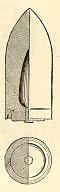 This projectile consists of
a cast-iron body having a double-lipped expanding
ring attached by a screw-thread to its base. Upon
discharge, the powder-gases entering the cannelure
of the ring expand the outer lip into the grooves
communicating rotation to the projectile, and
pressing the inner lip tightly against the base
of the projectile tends to prevent stripping. The
ring may be of brass (75 parts of copper to 25 of
tin) or of an alloy of copper, tin, and brass,
the brass being fuzed with the copper.
This projectile consists of
a cast-iron body having a double-lipped expanding
ring attached by a screw-thread to its base. Upon
discharge, the powder-gases entering the cannelure
of the ring expand the outer lip into the grooves
communicating rotation to the projectile, and
pressing the inner lip tightly against the base
of the projectile tends to prevent stripping. The
ring may be of brass (75 parts of copper to 25 of
tin) or of an alloy of copper, tin, and brass,
the brass being fuzed with the copper.
The Butler canister consists of a hollow cylinder made up of truncated iron wedges enclosed in an envelope of tin. The cylinder is closed at the bottom with a lead cup inclosing a disk of wood, and at the top with a sheet-iron plate, disks of tin being employed on the outside at both ends to facilitate soldering. The interior of the cylinder is filled with the round iron balls. See Expanding Projectiles and Projectiles.
CAISSON: A two-wheel cart carrying two ammunition chests and attached to a limber by a long pole. The limber also carried an ammunition chest and the entire unit was pulled by a six-horse team. Ammunition expended from the limber chest was replaced from the caisson chest. The specified number of rounds carried by each caisson and its limber was: for 6-pounder guns - 150 rounds; for 12-pounder guns - 96 rounds; for 12-pounder howitzers - 117 rounds; for 24-pounder howitzers - 69 rounds; and for 32-pounder howitzers - 45 rounds. When the limber chest was emptied, a replacement was carried forward from the caisson, which was usually parked to the rear of the battery. Caissons also carried a spare limber pole and wheel, pick axes, shovel, axe, and some miscellaneous tools. The number of caissons assigned to field batteries were: with a battery of 12-pounders - eight caissons for guns and four for howitzers; with a battery of 6-pounders - four caissons for guns and two for howitzers.
1. A carriage used to transport ammunition; in light field-batteries there is one caisson to each piece, in heavy batteries there are two. The ammunition is contained in three chests – two mounted on the body, and one on the limber. The number of rounds for each chest varies with the caliber of the piece, as follows, viz.:
| 6-pdr. Gun and 3-inch rifle-gun | 50 |
| 12-pdr. Gun | 32 |
| 12-pdr. Howitzer | 39 |
| 24-pdr. Howitzer | 23 |
| 32-pdr. Howitzer | 15 |
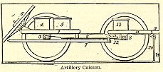 The
whole number of rounds for each piece may be
ascertained by multiplying the above numbers by
four. The caisson is composed of a body and a
limber. The body is composed of one middle and
two side rails (1), one stock (2), and one
axletree (3). It carries two ammunition-chests
(4, 5), a spare wheel (6), which fits upon an
iron axle-arm attached to the rear end of the
middle rail, one spare pole (7), fastened to the
under side of the stock, and a spare handspike.
The
whole number of rounds for each piece may be
ascertained by multiplying the above numbers by
four. The caisson is composed of a body and a
limber. The body is composed of one middle and
two side rails (1), one stock (2), and one
axletree (3). It carries two ammunition-chests
(4, 5), a spare wheel (6), which fits upon an
iron axle-arm attached to the rear end of the
middle rail, one spare pole (7), fastened to the
under side of the stock, and a spare handspike.
The spare articles are needed to replace broken parts. The caisson also carries a felling-axe, shovel, and pick-axe, to remove obstructions, repair roads, etc., a tarpaulin strapped on to the limber-chest, a tar-bucket, and a watering-bucket. See Field-carriages.
2. In engineering, a hollow box of iron or wood, open at the bottom, sunk where piers are to be placed. The largest caisson yet sunk was for the tower of the Brooklyn bridge on the New York side. At the bottom it was 172 feet long and 102 feet wide, with an air-chamber 9 ½ feet high, the roof 22 feet thick, and the sides carried up 82 feet from the lower edge. It had a cofferdam in the upper part; was built of timber lined with boiler-iron, and bolted together. In its construction there were used of lumber, board measure, 4,200,000 feet, and of iron, including bolts, 620 tons. When completed it weighed 13,271 tons, and there were 30,000 tons of masonry laid within it. There were two double air-locks extending into the air-chamber, in which were steam-pipes to keep an even temperature. Two shafts passed up through well-holes in the masonry, with an elevator in one and two spiral stairways in the other. Below the lowest edge of the caisson extended two water-shafts, each 7 8/4 feet in diameter, in which dredges and scoops grappled the stones and soil, raising their loads to cars above, which conveyed the refuse away. At the same time sand and fine dirt were blown out by air-pressure through forty or more pipes in various parts of the structure. The interior was illuminated by gas, and constant communication by telegraph was keep up with the workmen inside. There were four shafts, each 2 feet in diameter, for the introduction of material for the concrete with which the whole interior was finally filled. The caisson was sunk 78 feet below mean tide, a work that required a pressure of 34 pounds per square inch in addition to the normal pressure of air; and to supply this addition, thirteen large compressors were used. The earliest caissons for such purposes were used in England in 1738-40 in laying the foundations of the Westminster bridge over the Thames.
CALIBER: 1) The diameter of a cannon's bore expressed in inches, or the weight of the solid shot corresponding to it. 2) The inside diameter of a firing tube.
CALIPER: The caliper was used to measure lengths of time fuzes, fuze plugs, diameter of shot, and caliber of cannons. It was made of hinged sheet brass with steel points. A graduated scale along the side was set up in inches and divisions.
CANISTER: A metal cylinder made of tin, iron, or lead, with a removable thin iron top. A heavy iron plate is usually located between the canister balls and the wooden sabot at the bottom. The cylinder contains iron or lead balls which are arranged in rows with sawdust packed between them. The top edge of the vertical cylinder wall is bent over the iron top plate to help keep the canister contents in place and the bottom edge is nailed to the wooden sabot. Canister was designed to be used close range against enemy troops with the desired effect being that of a huge shotgun blast. It was recommended for use at ranges under 350 yards. A 12-pounder canister for the Napoleon smoothbore contained twenty-seven iron balls while the 12-pounder howitzer contained forty-eight iron balls. Canister was used in field, mountain, siege, and seacoast weapons.
CANISTER-SHOT: A canister-shot is a metallic cylinder about one caliber in length, filled with balls and closed at both ends with wooden or metal disks. They are supplied for all guns. For 8-inch canister, and all those of less caliber, the envelope is made of tin, while canister for the larger calibers have an envelope of iron. The bottom of 15-inch canister is made of two thicknesses of 1-inch hard wood, crossing each other, and put together with wrought-iron nails clinched. A spindle, with a wrought-iron handle passing through the center of the canister, is riveted on the bottom through a square plate. All other canister have bottom-heads of one thickness of hard wood. Top-heads are all made of white pine. The case is notched, turned over the heads, and tacked down. The balls for all canister are 1.3 inch diameter, and the number used varies with the caliber. To give more solidity to the mass, and prevent the balls from crowding upon each other when the piece is fired, the interstices are closely packed with sawdust. See Case-shot, Projectiles, Rifle-canister, and Siege and Garrison Ammunition.
CANNELURE: A groove cut or cast into the base of a projectile. This allowed lubricant or soft lead to be drawn down when the projectile traveled through the bore during firing.
CANNON: A general name for large pieces of ordnance or artillery, as distinguished from those pieces which can be held in the hand while being fired. No military weapon in use before the invention of gunpowder can fairly come under this designation; they were more generally of the kinds described under Balista. At what exact date cannon were first used is not known; but cannon, called "crakys of war," were employed by Edward III at Creecy, and at Calais in 1346. The first cannon or combards were clumsy, wider at the mouth than at the chamber, and made of iron bars hooped together with iron rings. The balls fired from them were first made of stone, afterwards superseded by iron. In the fifteenth century various kinds were known by the names of cannon, bombards, culverins, serpentines, etc. Bombards of great length and power were employed by Louis XI during his Flemish campaign in 1477, some with stone balls, some with iron. About this time cannon began to be made by casting instead of with hooped bars; and bronze or brass as a material began to be used as well as iron. The cannon of the sixteenth century were generally smaller, but better finished, than those of the fifteenth. The largest cannon made in the seventeenth century, so far as is known, was the Bejapoor cast-iron gun, "Malick e’ Meidan," or "Lord of the Plain," made either by Aurungzebe or by the Mahrattas; it was 14 feet long, 28 inches bore, and required a ball of 1600 lbs. weight. From the time of the great European wars in that century, cannon have undergone vast improvements, as well as the science and art of artillery necessary for their management.
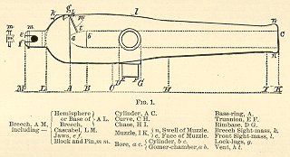 Cast-iron
cannon may generally be divided into five
principal parts, viz., Breech, Cylinder, Curve,
Chase, and Muzzle. The Breech is the mass of
solid metal in rear of the bottom of the bore:
the thickness is usually somewhat greater than
the greatest thickness of metal in the cylinder.
The Cylinder is that portion between the
base-ring and trunnions, including the seat of
charge and the point where the greatest strain is
exerted upon the gun. The Curve is the portion
connecting the cylinder with the chase. It is
made somewhat thicker than necessary to resist
the pressure of the powder, in order to serve as
a proper point of support for the trunnions, and
to compensate for certain defects of metal liable
to occur in the vicinity of the trunnions of all
cast cannon, arising from the crystalline
arrangement and unequal cooling of the different
parts. The Chase is the long, tapering portion of
the gun extending from the curve to the muzzle.
The principal injury to which the chase is liable
in smooth-bore guns arises from the striking or
balloting of the projectile against the side of
the bore; and the thickness of metal should be
sufficient to resist it. The Muzzle is the
increased thickness of metal which terminates the
chase. Inasmuch as the metal situated immediately
at the muzzle is supported under the direction of
the Secretary of War, with the general Signal
Service of the army; with the custody of all
records and apparatus connected therewith; with
the equipment and management of field-telegraphs
used with active forces in the field; with
constructing and operating lines of military
telegraph; with maintaining signal stations at
light-houses and at life-saving stations, and
with the observations and reports required by
law. The general nomenclature for cannon was:
knob, neck, vent, trunnion, muzzle swell, muzzle
face, muzzle, rimbase, cascable, breech, chamber,
and bore.
Cast-iron
cannon may generally be divided into five
principal parts, viz., Breech, Cylinder, Curve,
Chase, and Muzzle. The Breech is the mass of
solid metal in rear of the bottom of the bore:
the thickness is usually somewhat greater than
the greatest thickness of metal in the cylinder.
The Cylinder is that portion between the
base-ring and trunnions, including the seat of
charge and the point where the greatest strain is
exerted upon the gun. The Curve is the portion
connecting the cylinder with the chase. It is
made somewhat thicker than necessary to resist
the pressure of the powder, in order to serve as
a proper point of support for the trunnions, and
to compensate for certain defects of metal liable
to occur in the vicinity of the trunnions of all
cast cannon, arising from the crystalline
arrangement and unequal cooling of the different
parts. The Chase is the long, tapering portion of
the gun extending from the curve to the muzzle.
The principal injury to which the chase is liable
in smooth-bore guns arises from the striking or
balloting of the projectile against the side of
the bore; and the thickness of metal should be
sufficient to resist it. The Muzzle is the
increased thickness of metal which terminates the
chase. Inasmuch as the metal situated immediately
at the muzzle is supported under the direction of
the Secretary of War, with the general Signal
Service of the army; with the custody of all
records and apparatus connected therewith; with
the equipment and management of field-telegraphs
used with active forces in the field; with
constructing and operating lines of military
telegraph; with maintaining signal stations at
light-houses and at life-saving stations, and
with the observations and reports required by
law. The general nomenclature for cannon was:
knob, neck, vent, trunnion, muzzle swell, muzzle
face, muzzle, rimbase, cascable, breech, chamber,
and bore.
CANNON CREW: See Artillery Crew.
CANNON SIGHT: Generic term given to the different methods of aligning the piece and the equipment used to calculate and determine range and accuracy.
CANNONADE: 1) The report of heavy guns. 2) To attack with artillery.
CANNON BALL: See Solid Shot.
CANNONEERS: See Artillery Crew.
CAP OF A CANNON: See Apron.
CAP SQUARE: Iron plates which closed over the trunnions of a gun to secure it to the carriage.
CARCASS: Spherical shell which had four holes, the same size as a fuze hole, formed around the center at equal distances apart. The holes were filled with a combustible composition which burned with intense power for eight to ten minutes. The flame shooting from the holes set fire to everything combustible. Carcass was used in bombardments, to set fire to shipping, and to set fire to the enemy’s works.
CARRIAGE: Although the term may include the limber and caisson, the most common definition applies to the gun carriage. The carriage was designed to support the weapon when fired and, if movable, to transport it from place to place. Most field carriages were made of white oak and metal hardware. In the transportation mode the carriage was attached to a limber by means of a hook-and-eye arrangement. Siege (semi-permanent) and seacoast (permanent) carriages were usually wrought iron or heavy wood. Siege carriages were divided into two types - barbette or casemate - depending upon where they were mounted.
CARRONADE: A short naval gun of large caliber designed for firing at ships close together in action.
CARTRIDGE BAG: Also known as a Powder Bag. These bags were filled with black powder and were seated between the bottom of the bore and the base of the projectile. The bag was punctured by the priming wire, and a friction primer was inserted in the vent to allow the transfer of the spark to ignite the charge. Earlier in the Civil War, quick matches and slow matches were used to ignite the powder charge. Powder bags were made of a woolen material (merino, wildbore, or bombazette) completely free of cotton which had a tendency to retain fire. Flannel and paper were also used.
CASCABEL: That part of the cannon tube in the rear of the base ring. It was composed of the knob, neck, fillet, and the base of the breech. The cascabel was used to facilitate the handling of the piece when mounting and dismounting, and when moving it when it was off the carriage.
CASEMATE: A bomb-proof vaulted chamber with an embrasure for cannons. Casemates were constructed along the face and rear of a fort for service as quarters and hospital during engagements. A weapon mounted in this chamber was referred to as a casemate gun.
CASE-SHOT: Also known as spherical case-shot. Similar to the common shell except that the walls of the projectile were thinner. In both spherical and rifled projectiles, the bursting charge was usually located in a thin tin or iron container and placed in the center of the internal cavity. The case-shot was placed around this container. The cavity was usually filled with lead or iron balls in a sulphur or pitch matrix. The small bursting charge of black powder was designed to disperse the case-shot balls in a cone-shaped pattern. The concept was to give the same effects of canister, but at much longer ranges. Spherical case-shot was invented by an Englishman named Lieutenant Henry Shrapnel of the Royal Artillery in 1784. For an example of a cross-section of a case-shot projectile.
CAST IRON: A hard brittle, impure form of iron obtained by re-melting pig-iron with limestone. It was inflexible, but strong and rugged. Cast iron was used in production of artillery weapons and projectiles.
CAVETTO: See Molding.
CHAIN-SHOT: Two hemispheres, or round shots, connected together by a length of chain. In theory, when this shot was fired it began a rotation which was expected to be useful in cutting the masts and rigging of naval vessels. In reality these shots could hang up at the muzzle and swing around, killing or injuring the cannon crew.
CHAMBER: The smaller diameter section of the bore near the breech of the gun which held the propellant charge for the projectile. A cylindrical chamber, shaped like a smaller diameter bore at the bottom of the main bore, was used in howitzers. Its base was rounded or square. A conical chamber (also known as a Gomer chamber after its inventor), shaped like a frustum of a cone, was used in mortars. A spherical chamber, a sphere joined by a small diameter cylinder to the bore, was used in early mortars.
CHAMFER: To cast, cut, or grind a beveled edge into or on the opening of a tube or barrel.
CHARCOAL: The combustible ingredient in gunpowder made from wood burned in a special process.
CHARGE: See Powder Charge.
CHASE: The long, tapering portion of the tube which extended from the curve to the muzzle.
CHASE GUN: Also known as a Chaser. A gun mounted at the bow or stern of a naval vessel used when chasing or being pursued by another vessel.
CHASE RING: A molding at the front end of the chase. In brass weapons the chase ring was replaced with astragals and fillets.
CHASER: See Chase Gun.
CHASSIS: The traversing railway of iron or wood upon which a siege gun carriage rested in a casemate or barbette battery. It was also used for recoil or moving it to the front.
CHEEK: The side piece of the gun carriage which supported the trunnion.
CHEVAUX-DE-FRIZE: Sharp poles arranged in a manner which presented an obstruction to attacking infantry or cavalry. When manufactured, they were made of iron with a barrel 6-feet long and 4-inches diameter. The spears were 5-feet, 9-inches long. When constructed on the field, which was the most common method, they were made of logs 12-feet long and 10-inches thick and were drilled through every foot for sharpened stakes. The stakes were set at right angle to the pole and were about 3-feet long. The primary use of chevaux-de-frize was to obstruct gaps, stop a breach, or form a line of obstructions in front of a fortification or line of breastworks.
CHEVRETTE: A machine for hoisting heavy guns upon their carriages.
CHILL: A piece of iron introduced into a mold so as to rapidly cool the surface of molten metal which comes in contact therewith. Cast-iron, like steel, is hardened by rapid cooling, and softened by the prolongation of the cooling process. The extreme in the former direction gives chilled iron the hardness of hardened steel: the extreme in the direction of softness is obtained by prolonging the heat, abstracting the carbon from the cast-iron, reducing it to a nearly pure crystalline iron. See Bronze Guns.
CHILL-HARDENING: A mode of tempering steel cutting-instruments, by exposing the red-hot metal to a blast of cold air.
CHILLED-IRON: Used only in casting rifled solid shot projectiles. In this process the cast iron was poured into specially designed molds. The point of the projectile cooled rapidly in a thick cast iron chill while the body cooled more slowly in sand. The portion of the projectile cast in contact with the chill developed greater hardness, crushing strength, considerable brittleness, and increased density, without causing brittleness in that portion cooled in sand. The tip or point of a chilled projectile occasionally broke off on impact.
CHILLED PROJECTILES: Chilled-iron projectiles have been profitably employed to pierce armor-plates, on account of their intense hardness. The English projectiles recommended by Major Palliser may be described as an example of a chilled projectile. The form of these is cylindro-conoidal, the head being ogival, struck with a radius of 1 ½ diameters. The total length varies between 2 and 2 ½ calibers. The bottom is flat, and in the center of the bottom is a filling-hole for shells, closed with a composition screw-plug. All Palliser shells are lackered internally to give them a smooth, clean lining, which prevents the iron from either oxidizing at the expense of the powder, or firing it from friction by rapid rotation during flight. As the lacker does not always hold well to the metal, serge bags are introduced to contain the bursting-charge as an additional prevention against premature explosion. These bags are made bottle-shaped, and are introduced through the filling-hole. Palliser shot are cored. The hollow up the center enables them to cool more uniformly, and renders them less liable to split. It also slightly improves its proportions and its regularity of flight. The bottom is closed with a plug. These projectiles are made of carefully selected iron, which, if run in sand-molds, would solidify as mottled iron. The projectiles are cast point down, for the sake of density and soundness in the head. The mold is formed of a metal chill at the bottom extending up past the junction of head and body; the remainder of the mold is formed of sand, as also is the case for the formation of the interior. The chilling action therefore extends a little past the head of the projectile, which thus has a mottled body and a white head. The Gruson projectiles are cast with a dead-head on the base, which is afterwards cut off, the object being to obtain a solid bottom to stand well under the shock of the discharge. The chilling is effected by the metal molds, in virtue of their great conducting-power, their thickness greatly affecting the extent of their action. The head thus chilled white possesses generally the quality of white iron, intense hardness, crushing-strength, considerable brittleness, and increased density. The tip or point of a chilled projectile is occasionally broken off by the impact of a shell or shot rolled or struck obliquely against it; for the point which may penetrate directly through many inches of armor without injury may be fractured by a very slight transverse blow. See Projectiles and Steel Projectiles.
CHOCK: Also called Roller Chock. A small wedge with a handle on the side. It was used to chock, or bind, the wheels of permanently mounted gun carriages to prevent movement once the piece had been aligned and sighted.
COAST-BATTERIES: Batteries erected along a coast to protect the entrances of harbors and ports. They are armed with artillery of the largest caliber to oppose the landing of an enemy. The nature of ordnance for coast-defenses in England was in 1860 recommended to be as follows: the 10-inch gun of 86 cwt.; the 68-pdr. Of 95 cwt.; the 8-inch gun of 65 cwt.; the 32-pdr. Of 56 cwt.; the 13-inch sea-service mortar. Since the introduction of rifled artillery and armor-plated ships, the old smooth-bore guns, which formerly were used for coast-defense, have been superseded by the heavier rifled ordnance of the present day. See Ordnance.
COATED PROJECTILES: The surfaces of projectiles to which the lead covering is attached is smooth and the cannelures formerly in use to secure strength in the attachment of the lead are now omitted. The lead coating is held on by tinning, and at first cast on quite thick, but afterwards turned off in a lathe, leaving the usual projecting bands. The iron surface of the projectile is cast smooth, and then dipped in a solution of sal-ammoniac; after this it is immersed in a bath of melted zinc, and at the same time revolved on its long axis by means of an iron rod inserted in the fuze-hold. During this revolution, which is done by one workman, another presses a mass of sal-ammoniac, fastened to the end of an iron rod, on the surface of the projectile. After a sufficient amount of zinc is made in this way to adhere to the surface, the projectile is placed in an iron mold and the lead coating cast on it. The lead coat occasionally becomes detached in spots, where the lead has risen up into blisters from the formation of gas underneath it, occasioned by voltaic action between the different metals. Such blisters are generally very small, and may be pricked and then hammered down, without affecting the fitness of the projectile for service. If left to develop themselves, they have been known to attain a large size.
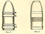 The
surface of the coating usually has raised bands
or welts to take the rifling of the piece. In the
German service the front band, a, as shown in
Fig. 1, is smaller in diameter than the others.
Next larger is the band b, then comes the band c,
and the largest in diameter of all is the rear
band, d. The lead coating is preserved from
injury by two grommets, which are nearly severed
to facilitate removal, and the projectiles are
stored in racks fitted in the shell-room.
Sometimes the body of the projectile is not
strictly cylindrical, but rather smaller at the
base, the lead coating bringing the finished body
into a cylinder. This form is considered good for
penetration, but any lead coating must
considerably retard the projectile in endeavoring
to force its way through armor.
The
surface of the coating usually has raised bands
or welts to take the rifling of the piece. In the
German service the front band, a, as shown in
Fig. 1, is smaller in diameter than the others.
Next larger is the band b, then comes the band c,
and the largest in diameter of all is the rear
band, d. The lead coating is preserved from
injury by two grommets, which are nearly severed
to facilitate removal, and the projectiles are
stored in racks fitted in the shell-room.
Sometimes the body of the projectile is not
strictly cylindrical, but rather smaller at the
base, the lead coating bringing the finished body
into a cylinder. This form is considered good for
penetration, but any lead coating must
considerably retard the projectile in endeavoring
to force its way through armor.
COLUMBIAD: A large diameter smoothbore cannon invented by Colonel Bomford and first used in the War of 1812. The Columbia Foundry in Washington, D.C., originally produced the piece, thus the name Columbiad. The Columbiad was a long, chambered piece, capable of projecting solid shot and shells, with heavy charges of powder, at high angles of elevation. They were equally suited to the defense of naval batteries along the coastal waterways and navigable rivers. These pieces were also mounted on wooden ships, ironclads, and monitors. Three calibers of Columbiads were used in battle; the 8-inch (weight 9,240 pounds and 124 inches long), the 10-inch (weight 15,400 pounds and 126 inches long), and Captain T.J. Rodman’s massive 15-inch Columbiad (weight 49,100 pounds and 190 inches long). A 12-inch and 20-inch Columbiad was also developed, but never employed in battle.
COLUMBIADS: A species of sea-coast cannon
which combine certain qualities of the gun,
howitzer, and mortar; in other words, they are
long, chambered pieces, capable of projecting
solid shot and shells, with heavy charges of
powder, at high angles of elevation, and are,
there-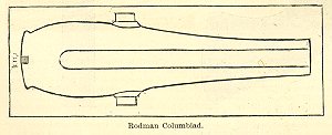 fore,
equally suited to the defense of narrow channels
and distant roadsteads. The Columbiad was
invented by the late Colonel Bumford, and used in
the War of 1812 for firing solid shot. In 1844
the model was changed, by lengthening the bore
and increasing the weight of metal, to enable it
to endure an increased charge of powder, or 1/6
of the weight of the solid shot. Six years after
this it was discovered that the pieces thus
altered did not always possess the requisite
strength. In 1858 they were degraded to the rank
of shell-guns, to be fired with diminished
charges of powder, and their places supplied with
pieces of improved model. The changes made in
forming the new model consisted in giving greater
thickness of metal in the prolongation of the
axis of the bore, which was done by diminishing
the length of the bore itself; in substituting a
hemispherical bottom to the bore, and removing
the cylindrical chamber; in removing the swell of
the muzzle and base-ring; and in rounding off the
corner of the breech. From the fact that all the
trial-pieces have successfully endured very
severe tests, it is to be inferred that the
defects of the previous model arose from the
presence of a cylindrical chamber, and a
deficiency of metal in the prolongation of the
bore. In 1860 the model proposed by Captain
Rodman was adopted for all sea-coast cannon. This
model is shown in the drawing; it does not
differ, however in its essential particulars from
the model of 1858. See Sea-coast Artillery.
fore,
equally suited to the defense of narrow channels
and distant roadsteads. The Columbiad was
invented by the late Colonel Bumford, and used in
the War of 1812 for firing solid shot. In 1844
the model was changed, by lengthening the bore
and increasing the weight of metal, to enable it
to endure an increased charge of powder, or 1/6
of the weight of the solid shot. Six years after
this it was discovered that the pieces thus
altered did not always possess the requisite
strength. In 1858 they were degraded to the rank
of shell-guns, to be fired with diminished
charges of powder, and their places supplied with
pieces of improved model. The changes made in
forming the new model consisted in giving greater
thickness of metal in the prolongation of the
axis of the bore, which was done by diminishing
the length of the bore itself; in substituting a
hemispherical bottom to the bore, and removing
the cylindrical chamber; in removing the swell of
the muzzle and base-ring; and in rounding off the
corner of the breech. From the fact that all the
trial-pieces have successfully endured very
severe tests, it is to be inferred that the
defects of the previous model arose from the
presence of a cylindrical chamber, and a
deficiency of metal in the prolongation of the
bore. In 1860 the model proposed by Captain
Rodman was adopted for all sea-coast cannon. This
model is shown in the drawing; it does not
differ, however in its essential particulars from
the model of 1858. See Sea-coast Artillery.
COMBINATION FUZE: Combination of the time fuze and percussion fuze system. The inertia of firing caused the plunger in the fuze to strike a chemical composition, thereby igniting the powder train. The fuze was designed to act as a percussion fuze if it struck an object before the pre-set time. Examples of combination fuzes can be found on Armstrong, Schenkl, and Sawyer projectiles, among others.
COMMON SHELL: See Shell.
COMPRESSION-PROJECTILES: The systems under
this class differ in the nature and arrangement
of the metal to be compressed. Solid shot,
shells, and shrapnel can be used in each. A
projectile of this system is composed of a
cast-iron or steel body, and of a lead coating
cast over and between rings projecting from the
body of the projectile. Bands of lead,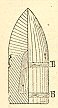 extending
beyond the general surface, are compressed by the
lands as the projectile is forced through the
bore of the piece. A construction more generally
used is to have the body smooth, and to attach
the coating chemically; to accomplish this, the
body is thoroughly cleaned, and immersed in a
solution of sal-ammoniac; next it is covered with
powdered sal-ammoniac, and dipped first into
melted zinc and afterwards into melted tin; it is
then placed in a metal mold and the lead cast
upon it. The hold in the base is closed by a
screw-plug, which has a ring for handling the
projectile and for extracting it from the piece
when necessary.
extending
beyond the general surface, are compressed by the
lands as the projectile is forced through the
bore of the piece. A construction more generally
used is to have the body smooth, and to attach
the coating chemically; to accomplish this, the
body is thoroughly cleaned, and immersed in a
solution of sal-ammoniac; next it is covered with
powdered sal-ammoniac, and dipped first into
melted zinc and afterwards into melted tin; it is
then placed in a metal mold and the lead cast
upon it. The hold in the base is closed by a
screw-plug, which has a ring for handling the
projectile and for extracting it from the piece
when necessary.
In the French system these projectiles have two bands, B and B, of copper, attached by being forced into annular undercuts as shown in the drawing. To favor the compression, triangular grooves are cut around the surface of the bands. The forward band is placed near the center of gravity of the projectile; its diameter is only about .02 inch greater than the caliber of the piece, and therefore does not assist in giving rotation, but only in centering the projectile; the accuracy of fire is thereby increased, but the velocity at the muzzle of the piece is slightly reduced. See Coated Projectiles, French Projectiles, and Projectiles.
COMPRESSIVE SYSTEM OF RIFLING: This system embraces all projectiles which are loaded in a chamber and then forced by the action of the powder through the bore of the gun, the diameter of which across the lands is less than the superior diameter of the projectile. Projectiles of this class are necessarily confined to breech-loading guns, and, as the name of their class implies, take the grooves by compression. The general character of the rifling in breech-loaders consists in a great number of shallow grooves usually narrowing toward the muzzle to make up for the slip and abrasion of the leaden jacket of the projectile. The Armstrong system of rifling for breech-loaders, formerly used in the English service, does not differ in principle from this. The rifling consists of a great number of shallow, narrow grooves (the 7-inch has 76), the object being to give the soft-metal covering a very large baring on the driving-side of the grooves, and thus prevent stripping, and make up for want of depth. See System of Rifling.
CONCUSSION FUZE: A chemical fuze designed to activate from the shock of striking an object. The chemicals were kept separate until impact when the action of the chemicals upon each other caused a flame. Examples of this type of fuze are the Confederate Broun and the Federal Tice Concussion fuze.
CONE: 1) The actual percussion system found in projectiles armed with percussion fuzes. The function of the cone was to support the percussion cap when exploded by the slider and transfer the flame to the powder system. The percussion cap sat on a nipple on one end of the cone. Also used in small arms such as muskets, rifles, and pistols. 2) The tapered rear portion of a projectile.
CONE OF DISPERSION: The cones of dispersion of projectiles comprise all the causes of error in firing, whether resulting from the arm itself, from the projectile and the resistance of the air, or from the want of practice or skill in the marksman. The causes of irregularity in firing, although greater in the horizontal than in the vertical direction, are considerable in the latter. They raise or depress the projectiles, and change the ranges to an appreciable extent. The general form of the cone of dispersion will present a curved surface, which is concave outwards; for experiment goes to prove that when a variable cause acts an infinite number of times, the variations of this cause tend to neutralize each other, and we may then assimilate its effects to those of a constant accelerating force, acting in the same manner as gravity. The separation of the projectiles is not in proportion to the ranges, but increases more rapidly. The cone of dispersion becomes longer, with equal deviations, as the velocity of the projectiles increases; or in other words, the fire is more accurate as the velocity is increased. Ancient artillerists were aware of this principle, and in consequence employed for small-arms charges much larger than those now in general use.
CONFEDERATE PROJECTILES: The rifle-projectiles
used by the Confederates in the late war
belonged, with a few exceptions, to the expanding
class.
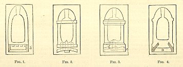
Fig. 1 presents a shell with a copper ring (b)
fitting into a rabbet formed around its base in
casting. This projectile would seem to resemble
the Parrott projectile in its construction. The
lower edge of the band, however, projects below
the bottom the base, which in Parrott’s it
does not. Recesses are formed in the sides of the
rabbet to prevent the ring from turning.
The projectile represented in Fig. 2 has a thick circular plate of copper attached to its base by means of a screw-bolt at its center. To prevent it from turning around this bolt there are three pins, or dowels, fastened into the base of the projectile, and projecting into corresponding holes in the circular plate. This plate is slightly cupped, and the angle between it and the bottom of the projectile is filled with a greased cord for lubricating the bore of the gun. This projectile is referred to as a "Tennessee Cup or Sabot" and often called a "Mullane" shell.
Fig. 3 represents a projectile of the Brooke class, with its expanding cup of copper (a). Instead of the soft-metal studs which are placed on the forward part of the Brooke projectile, this projectile has a raised band carefully turned to fit the bore.
Fig. 4 represents a Read projectile, in which the expanding cup is made of copper, as shown at a. This cup is placed in the mold, and the body of the projectile is cast upon it. See Expanding Projectiles and Projectiles.
CONSTRUCTION: A term defined by the authors that is used to describe the interior design of a projectile.
CORED SHOT: A projectile with an empty hollow interior. The entrance hole to the empty interior was plugged with a wooded peg to keep out water. This type of shot was designed to be fired from Dahlgren smoothbores against masonry fortifications. The theory behind cored shot was that it decreased the strain on the gun and increased the velocity of the shot.
COUNTER-BATTERY: A number of guns placed behind a parapet with the primary purpose of dismounting or silencing the guns in an enemy’s work by using direct fire. This tactic was also used by field artillery.
CREMAILLERE: Also known as Indented Line. The cremaillere was made up of a number of salients and was used in simple entrenched fortifications. This position was often the target of heavy artillery bombardments.
CROW: A bar of iron used as a lever in naval gun exercises.
CURVE: That portion of the cannon tube connecting the cylinder with the chase.
CYLINDER: That portion of the bore between the base ring and trunnions, including the seat of the charge. The point of the greatest strain exerted upon the gun. This area included the reinforce.