Artillery Glossary
F Terms
 All projectiles should be cast in
sand and not in iron molds, as those from the
latter are seldom uniform in size or shape, are
liable to contain cavities, and are cracked if
heated. Sand possessing all the properties to be
desired for molding is seldom, if ever, found in
a state of nature. But, when the requisite
qualities are known, the materials may be
selected and an artificial composition produced
without difficulty. The sand should be silicious,
refractory, and of an angular grain of moderate
size. The degree to which the first and second
qualities should be possessed depends upon the
size of the casting; the sand must not be fuzed
or even softened by the heat to which it is
subjected. The angular form and large size of the
particles increase the resistance of the mold,
though rendering it less compact; this last
facilitates the evaporation of the moisture in
drying, and permits the escape of the gases
formed in the material of the mold by the heat of
the fuzed metal. Pit- and not river-sand should
be used, as the latter is not sufficiently sharp
or cohesive.
All projectiles should be cast in
sand and not in iron molds, as those from the
latter are seldom uniform in size or shape, are
liable to contain cavities, and are cracked if
heated. Sand possessing all the properties to be
desired for molding is seldom, if ever, found in
a state of nature. But, when the requisite
qualities are known, the materials may be
selected and an artificial composition produced
without difficulty. The sand should be silicious,
refractory, and of an angular grain of moderate
size. The degree to which the first and second
qualities should be possessed depends upon the
size of the casting; the sand must not be fuzed
or even softened by the heat to which it is
subjected. The angular form and large size of the
particles increase the resistance of the mold,
though rendering it less compact; this last
facilitates the evaporation of the moisture in
drying, and permits the escape of the gases
formed in the material of the mold by the heat of
the fuzed metal. Pit- and not river-sand should
be used, as the latter is not sufficiently sharp
or cohesive.
The molding composition must contain such an amount of clay that, when slightly moistened, it will retain its shape when pressed in the hand; it must become hard when dried that it may not lose the form given it, and must possess the consistence necessary to resist the pressure of the liquid metal. As clay contracts by heat, an excess of it will cause cracks in the mold in drying. The manner of preparing the composition is usually to mix fire-sand and loam or field-sand, to sift it carefully, and then to moisten it with water in which clay has been stirred. The particular sand to be employed, and the proportion of clay to be introduced, depend upon the size of the casting.
Spherical Projectiles – Case-shot shell, and all solid shot smaller than the 15-inch are cast singly. Fifteen- and twenty-inch solid shot are usually cast in clusters of five and three respectively.
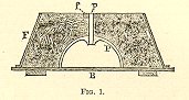
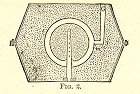
When cast singly the pattern of a spherical projectile is composed of two hollow cast-iron hemispheres, uniting in such a manner as to form a perfect sphere; on the interior of each hemisphere is a handle by which it is withdrawn from the sand after molding. The flask has neither top nor bottom, or has movable ones; it is usually in two parts, joining the same plane as the pieces of the pattern. In molding a shell (Figs. 1 and 2), the pattern, P, of that half in which is situated the fuze-hole is placed with its flat side upon the molding-board, B; this is covered with its corresponding half of the flask, F; the spindle (p), attached to the pattern, passes through a hole in the cross-piece (f) of the flask. Powdered charcoal or fine dry sand is sprinkled over the board and pattern, to prevent the fresh sand from adhering to these surfaces. The molding-sand is then introduced gradually into the flask being well rammed as it rises up about the pattern. When completed, this portion of the flask with its contents is turned over on a board, the other half of the pattern placed upon that already in position, and the second part of the flask laid on the first and properly fitted thereto. The pattern and the exposed surface of the mold are sprinkled as before, and the molding continued, a conical stick having first been so placed as to form the "gate," G, for the introduction of the molten metal. The flask having been filled, the two parts are separated; each now contains one half the mold with the corresponding part of the pattern. The stick for the gate is withdrawn from the outside, and the hemispheres are extracted from the inside. A channel is cut in the plane surface from g to m, so that the metal, entering at G, may be carried to the mold-cavity at a point where it can flow into place without injury to the surface of the sand. Any imperfections are at this time repaired. The whole interior surface is then coated with a wash of powdered coke and clay-water, after which the mold is thoroughly dried in an oven. This wash gives a smooth, hard surface to the sand, which insures a smooth casting.
 The
core is formed about a hollow iron spindle,
perforated with small holes through which escape
the steam and gases generated by the heat of the
metal. The core is centered in the mold by means
of a gauge, and is supported in that position by
the spindle which forms the fuze-hole. The
spindle is perforated with small holes to allow
the escape of steam and gas generated by the heat
of the melted metal; that part of it which forms
the fuze-hole is coated with sand to prevent
adhesion. When the ears for the shell-hooks are
cast in the projectile the necessary projections
for their formation are placed in position before
drying the mold. In pouring the melted iron into
the mold with the ladle, care should be taken to
prevent scoria and dirt from entering with it,
and for this purpose the surface should be
skimmed with a stick of wood. After the iron has
become sufficiently hardened the flask is
removed, the sprue-head is broken off, and the
composition scraped from the outside of the
casting. The core is then broken up and removed,
and the interior surface cleaned by a scraper.
The projection at the gate and other
excrescencies are next chipped off and the
surface of the projectile is smoothed in a
rolling-barrel, or with a file or chisel if found
necessary. The fuze-hole is then reamed out to
the proper size and the projectile is ready for
inspection.
The
core is formed about a hollow iron spindle,
perforated with small holes through which escape
the steam and gases generated by the heat of the
metal. The core is centered in the mold by means
of a gauge, and is supported in that position by
the spindle which forms the fuze-hole. The
spindle is perforated with small holes to allow
the escape of steam and gas generated by the heat
of the melted metal; that part of it which forms
the fuze-hole is coated with sand to prevent
adhesion. When the ears for the shell-hooks are
cast in the projectile the necessary projections
for their formation are placed in position before
drying the mold. In pouring the melted iron into
the mold with the ladle, care should be taken to
prevent scoria and dirt from entering with it,
and for this purpose the surface should be
skimmed with a stick of wood. After the iron has
become sufficiently hardened the flask is
removed, the sprue-head is broken off, and the
composition scraped from the outside of the
casting. The core is then broken up and removed,
and the interior surface cleaned by a scraper.
The projection at the gate and other
excrescencies are next chipped off and the
surface of the projectile is smoothed in a
rolling-barrel, or with a file or chisel if found
necessary. The fuze-hole is then reamed out to
the proper size and the projectile is ready for
inspection.
When shot are cast in clusters, the pattern is made of wood and consists of two longitudinal halves, which are fitted with iron pins or dowels so that they can be accurately joined together for the construction of the mold. The cluster is cast with a sinking-head to feed the shrinkage, while the shot are made with a diameter slightly in excess of the required one, to permit of their being turned down and finished. The flask is also made in two equal parts or sections which are united by bolts. The back of each section is fitted with movable plates, to admit of the introduction to the molding composition. To form the mold, one half of the pattern is laid upon the molding-board, together with the pattern for one half of the channel for the metal, both being held in place by dowels. A section of the flask is then placed in position over the patterns, and the intervening space is filled with molding composition, which is firmly rammed down, the patterns for the branches to the channels being introduced as the work progresses. The plates are then attached in their places. To form the other section of the mold, the finished one is removed from the molding-board and turned over, the remaining halves of the patterns and flask are placed in position upon it, and the molding composition filled in the same manner. A layer of dry sand is first sprinkled over the surface of the finished section to prevent adhesion. The Mold being completed, the two sections are separated and the patterns withdrawn. After being thoroughly dried in an oven and receiving a coating of coke wash on the interior surface, the sections are united and firmly secured together with bolts and nuts. The mold is then ready for the casting and is lowered into the pit. Several clusters are usually cast with one heat of metal, the number depending upon the capacity of the furnace. The casting is usually allowed to remain in the pit for twelve or fifteen hours after the pouring of the metal, when it is hoisted out and taken from the flask. After it becomes cool it is freed from the adhering composition and the gates are broken off.
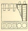
To separate the shot in the cluster, the
latter is placed in a lathe, shown in Fig. 3, the
sinking-head being secured in the chuck at the
head of the machine, while the other end is
supported by a movable center which slides upon
the ways. When the cluster is properly centered
the necks which connect the shot are turned down
as small as it is safe to make them without
risking the breaking of the cluster in the lathe.
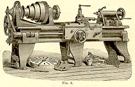 The neck
nearest to the bottom is then carefully turned
down until it begins to show indications of
breaking. The cluster is then chocked up by
placing blocks between it and the lathe-bed, the
center is slid back, and the shot is broken off
by blows with a hammer and removed. The cluster
is then re-centered in the lathe, and the shot
are successively detached in a similar manner
until all are separated. Care should be taken to
preserve, as far as practicable, a spherical form
to that portion of the surface where the neck is
turned away. The small portions of the necks
which remain after the separation are chipped off
by hand. The shot is next turned down to the
required diameter and given a smooth and finished
surface. The tool-rest of this lathe is attached
to a geared wheel, which is pivoted in a
horizontal position upon an iron frame secured to
the lathe-bed. The motion of this wheel by means
of a feed causes the edge of the tool to move on
the arc of a circle, its distance from the center
of the circle meanwhile being regulated by a
screw in the base of the rest. The shot is
centered in the lathe by means of a square-headed
screw in the axis of the wheel. In turning the
shot it is made to revolve upon that diameter
which coincides with the axis of the lathe, while
the movement of the tool-rest, as above
described, brings the tool in contact with all of
the surface which is not covered by the supports.
In this position the shot is finished as far as
practicable, and is then re-centered so that the
unturned portions of the surface can be brought
in contact with the tool, when they are finished
in like manner. The ears for the shell-hooks are
then drilled in a drilling-machine and the shot
is ready for inspection. Fifteen- and twenty-inch
shell are sometimes cast above size and finished
in the lathe in the same way as cluster-shot.
The neck
nearest to the bottom is then carefully turned
down until it begins to show indications of
breaking. The cluster is then chocked up by
placing blocks between it and the lathe-bed, the
center is slid back, and the shot is broken off
by blows with a hammer and removed. The cluster
is then re-centered in the lathe, and the shot
are successively detached in a similar manner
until all are separated. Care should be taken to
preserve, as far as practicable, a spherical form
to that portion of the surface where the neck is
turned away. The small portions of the necks
which remain after the separation are chipped off
by hand. The shot is next turned down to the
required diameter and given a smooth and finished
surface. The tool-rest of this lathe is attached
to a geared wheel, which is pivoted in a
horizontal position upon an iron frame secured to
the lathe-bed. The motion of this wheel by means
of a feed causes the edge of the tool to move on
the arc of a circle, its distance from the center
of the circle meanwhile being regulated by a
screw in the base of the rest. The shot is
centered in the lathe by means of a square-headed
screw in the axis of the wheel. In turning the
shot it is made to revolve upon that diameter
which coincides with the axis of the lathe, while
the movement of the tool-rest, as above
described, brings the tool in contact with all of
the surface which is not covered by the supports.
In this position the shot is finished as far as
practicable, and is then re-centered so that the
unturned portions of the surface can be brought
in contact with the tool, when they are finished
in like manner. The ears for the shell-hooks are
then drilled in a drilling-machine and the shot
is ready for inspection. Fifteen- and twenty-inch
shell are sometimes cast above size and finished
in the lathe in the same way as cluster-shot.
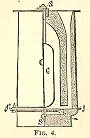
Elongated Projectiles – The same
principles are followed in the different
operations attending the fabrication of elongated
as of spherical projectiles. The shape and
construction of the flask and pattern depend upon
the particular form of the projectile, the system
to which it belongs, and the object for which it
must be employed. The construction applied in the
fabrication of a Parrott shell is shown in Fig.
4; the flask and pattern are each in two parts,
united along the plane (f, f); the ring (m), of
molding-sand, is made in a special box; and is
inserted when the mold is assembled before
casting, and is necessary to give the shape
peculiar to that system of projectiles. The
spindle, S, as in all the large oblong shells,
passes entirely through the core, C, and is
secured at both ends to the flask, or to the
mold. The metal is taken from the cupola into the
ladles, and, in the case of chilled shot, usually
slightly cooled by throwing in a piece of
scrap-iron. This is done to prevent the
chill-molds from being cracked.
 The metal
enters the mold from below, near and above the
chill-mold, and (from the shape of the lower
branch of the "feeder") in an oblique
direction, to avoid disturbing the core and to
give a circular motion to the metal as it rises
in the mold, and so prevent the scoria from
adhering to the sides. One workman skims the
surface of the metal with a wooden stick, as it
runs from the ladle, to prevent the admission of
the scoria, while another stirs it as it rises,
with an iron rod, through the "riser,"
to bring the impurities to the surface. Before
fairly cooled the flasks are removed, the sand
knocked off, the core-stem extracted, and the
shot left to cool in the heated sand in which it
was cast, The sand is now carefully scraped from
the cavity, the sinking-head is removed, and the
rough edges trimmed off with a cold-chisel. It is
then examined as to quality and weight, and the
amount of eccentricity roughly determined. The
shot is at once condemned if there be a variation
in any of these particulars in excess of that
allowed. It sometimes happens, too, that the
chill has extended so far over the surface as to
make it impossible to finish the shot by the
means ordinarily employed in this country. Such
shot are, however, sometimes finished by the
grindstone. Having passed this preliminary
inspection, it is put in the lathe and turned
down to the true diameter for the length of .25
inch. The shot is finally passed through the
finishing-press, and placed in a lathe where the
base is finished; if the Butler sabot is to be
used, a screw-thread is cut upon the base. The
sabot is usually formed of an alloy of 70 parts
copper and 30 of zinc. It is either cast
separately or directly upon the base of the
projectile; in the former case it is bored and
turned to the finished size. The shot is
completed by tapping a thread on the screw-plug
hole, fitting it with a plug, and screwing or
casting on the sabot. See Core-box,
Finishing-press, and Projectiles.
The metal
enters the mold from below, near and above the
chill-mold, and (from the shape of the lower
branch of the "feeder") in an oblique
direction, to avoid disturbing the core and to
give a circular motion to the metal as it rises
in the mold, and so prevent the scoria from
adhering to the sides. One workman skims the
surface of the metal with a wooden stick, as it
runs from the ladle, to prevent the admission of
the scoria, while another stirs it as it rises,
with an iron rod, through the "riser,"
to bring the impurities to the surface. Before
fairly cooled the flasks are removed, the sand
knocked off, the core-stem extracted, and the
shot left to cool in the heated sand in which it
was cast, The sand is now carefully scraped from
the cavity, the sinking-head is removed, and the
rough edges trimmed off with a cold-chisel. It is
then examined as to quality and weight, and the
amount of eccentricity roughly determined. The
shot is at once condemned if there be a variation
in any of these particulars in excess of that
allowed. It sometimes happens, too, that the
chill has extended so far over the surface as to
make it impossible to finish the shot by the
means ordinarily employed in this country. Such
shot are, however, sometimes finished by the
grindstone. Having passed this preliminary
inspection, it is put in the lathe and turned
down to the true diameter for the length of .25
inch. The shot is finally passed through the
finishing-press, and placed in a lathe where the
base is finished; if the Butler sabot is to be
used, a screw-thread is cut upon the base. The
sabot is usually formed of an alloy of 70 parts
copper and 30 of zinc. It is either cast
separately or directly upon the base of the
projectile; in the former case it is bored and
turned to the finished size. The shot is
completed by tapping a thread on the screw-plug
hole, fitting it with a plug, and screwing or
casting on the sabot. See Core-box,
Finishing-press, and Projectiles.
FACE OF THE PIECE: The surface, or plane, at the extremity of the muzzle or trunnions.
FAIRING: Architectural blending of surfaces in artillery pieces to create a smooth outline instead of abrupt joints. This helped reduce stress in the weapon.
FASCINE: 1) Long bundle of green brushwood tied together. Fascines were placed closely together in entrenchments, epaulements, and revetments of parapets to support the earthen walls. They were also used for covering wet or marshy ground. Fascines ranged in length from 6- to 18-feet. 2) Fascines were also made of dry twigs tied together and covered with pitch to be used as torches.
FIELD AMMUNITION: Projectiles designated for use in field artillery pieces. This category consisted of solid shot, shell, canister, and case-shot.
FIELD ARTILLERY: Artillery piece designated for use in the field. The essential quality of field artillery was mobility, and it was used in combination with the infantry and cavalry to augment their fire. Field artillery prepared the way for operations by firing at the enemy while he was still out of range of other weapons. It also served as a point of support and assembly when troops were driven back. Examples of field artillery included the 3-inch Wrought-iron (Ordnance) rifle, the 6-pounder (3.67-inch caliber) smoothbore, 12-pounder (4.62-inch caliber) Napoleon smoothbore cannon, the 20-pounder Parrott and the 4.5-inch Siege rifle, the largest gun in the field artillery of the Civil War. Field-cannon are intended to be used in the operations of an army in the field; they should therefore, have the essential quality of mobility. They are divided into light and heavy pieces. The former are constructed to follow the rapid movements of light troops and cavalry. The latter are employed to follow the movements of heavy troops, to commence an action at long distance, to defend field-works and important positions on the field of battle, etc.; hence they are said to constitute "batteries of position." Formerly the light pieces of the field-service of the United States were the 6-pounder Gun and 12-pounder Howitzer; and the heavy pieces were the 12-pounder Gun and 24-pounder and 32-pounder Howitzers. At the commencement of the late war in this country, these pieces were set aside for arming field-works, block-houses, etc., and their places were supplied with the light 12-pounder Gun (smooth-bore) and the 3-inch rifle-gun. The regulations prescribe that, as a general rule, one third of the pieces of a field-battery be rifles and the remainder smooth-bores. Of course this proportion is subject to be modified by the character of the operations and the nature of the country. The country in which most of our late military operations were conducted was either broken in surface or heavily wooded, and the most effective fighting was done at moderate ranges, at which the light 12-pounder, with its heavy shell and case-shot, was found more destructive than the 3-inch rifle-gun.
Field artillery is used in combination with infantry and cavalry, or with both, to augment their fire and to weaken that of the enemy. It prepares the way for subsequent operations by its fire upon the enemy before he comes within reach of other weapons; it supports the maneuvers of the various arms, and forms points of support and assembly for troops when driven back. In selecting the position for a battery, the ground must be considered both in plan and profile. The guns must be placed neither too high nor too low. Late wars have shown that it is not alone desirable but necessary to cover the guns and horses of a battery from the enemy’s fire, either by the accidents of the ground or by improvised cover; for nothing else can insure the battery against destruction by the enemy’s infantry and artillery. The range, accuracy, and rapidity of fire of small-arms of the present day are such that batteries which have been brought into action with the greatest possible rapidity have been placed hors du combat before firing a shot. The most favorable position is a gentle hillock, sloping gradually to the front and more abruptly to the rear, with a command over the ground occupied by the enemy of about 1 in 100. Considering the ground in plan, guns may be drawn up with good effect behind a marsh, pond, or river or ravine, provided such obstacles do not render an advance impracticable, and the ravine be not occupied by the enemy. The guns should not be in the neighborhood of woods, brush, or other cover that can be occupied by the enemy. Heavy, muddy ground, as well as that which is stony, should be avoided. The ground for 50 to 100 yards in front of the battery should be as unfavorable as possible for the enemy’s artillery-fire.
The extreme range should be employed only when the nature of the ground or the shortness of the time does not permit a nearer approach to the object, and then only till the effect desired has been obtained. With rifled pieces this fire may exceed 5000 or 6000 yards. It may annoy troops in their camp, may impede the movement of trains, and endanger inflammable buildings and materials, but cannot affect an action; therefore, to open fire beyond the limit at which the effect can be ascertained by good sight, aided by telescopes, is a waste of valuable ammunition. If the ground and atmosphere be favorable, and the range can be determined accurately, fire may be opened against troops at 2500 yards, and under exceptional circumstances at 3000 yards; the former is about the distance at which bodies of troops can be distinguished with certainty by the best eye. This distance is modified by the formation of the troops; a column can be fired at effectively 500 yards beyond troops in line. At long range the object must be well defined, the distance carefully determined, and the firing calm and very deliberate. As a battery cannot withstand the fire of small-arms, artillery without cover cannot now maintain a position within 900 yards of the enemy’s infantry.
The object selected upon which to direct the fire depends upon the nature of the action. In acting offensively, the fire should be directed upon that arm of the enemy which most immediately threatens us. Definite rules cannot be given for what must practically be decided almost entirely by the peculiar circumstances of the individual case. The nature and position of the object fired at determine the projectile to be used. The employment of solid shot is growing greatly into disuse; with rifled guns it is but little used, and in many services is entirely discarded, as the shell and shrapnel as now constructed are sufficiently strong and heavy to replace it and produce far more ultimate effect. It may be useful in firing over troops, but even then shells, preferably with percussion-fuze, can be employed. Shells are used at first to determine the range; for this, percussion-fuzes are best if the nature of the ground permit. This fire is used to disable artillery; against columns of troops, or when a line can be enfiladed or taken obliquely; against obstacles, such as intrenchments and buildings, and against combustible materials. If the shell be intended for incendiary purposes, a time-fuze cut long is employed. Should the distance be accurately known and the time-fuze burn uniformly, such a fuze can be advantageously used; but generally a percussion-fuze is more useful. The nature of the ground is of little importance only at the spot where the shell strikes; there it should be firm enough to cause a percussion-fuze to act and to prevent the shell from penetrating so far as to lose its explosive effect. Shell-fire is employed when the enemy is posted under cover, or on a higher or lower ground; when he is moving on a road through a valley, and when being pursued; when the ground is much broken, wooded, or cannot be seen; when the range is too great for effective shrapnel fire; for incendiary purposes, and when a moral rather than a physical effect is desired.
In the fire of shrapnel and segment shells, it is of more importance to have a knowledge of distance than of the nature of the ground, as the elevation must be properly taken and the fuze correctly timed. If such a projectile explode after passing the object, its effect is entirely lost; and if it explode too far short, the effect is greatly diminished; therefore the aim should be taken a little short of the object, that it may be the more readily corrected. The spread of the pieces being greater in the direction of the fire than laterally, these projectiles are more effective against high, deep objects than against broad, flat ones; they are therefore more destructive against cavalry in column than in line, and more so against either than against infantry in column or in line. Shrapnel-fire is also employed against troops dispersed or scattered; against troops in defiles or openings, or massed at points. It is effective against artillery in position, especially when it can be taken obliquely; time-fuzes should be used against the animate objects, and percussion-fuzes against the material. Time- or percussion-fuzes can be employed against troops in column or in line; but if they be scattered, time-fuzes only should be used. Well-applied shrapnel-fire is more effective than any other artillery-fire against troops, but it is subject to so many contingencies, and the ammunition is so costly, that it should not be employed unless it will probably create considerable effect, and when other projectiles will not answer. The possibility of shrapnel exploding in the piece causes great care to be necessary in firing over the heads or through the intervals of the troops. The fire of canister-shot is confined to ranges within 500 yards, and is rarely of any effect beyond 350 yards. The nature of the surface has a great influence on the utility of this fire; it is largely diminished on rough or soft ground, especially if covered with bushes or standing crops, and is increased on hard, level ground. As batteries can no longer move up to short range of troops and open fire with canister, its use offensively is entirely ended. On the defense, it is used to most advantage against troops in column whose front is greater than thirty or forty fee; it is useful against scattered or dispersed troops at short ranges, and against the attack of field-entrenchments, villages, and the skirts of woods. In cases of great emergency, a double charge of canister, fired with a single cartridge, may be used for distances within two hundred yards. A canister-fire should not be used too early, as, if ineffective, it destroys the confidence of the troops and increases that of the enemy. It does not always produce the desired effect: 1st, because the distance is underestimated; 2d, sufficient care is not taken in aiming, because the danger is exaggerated; 3d, the character of the ground is not properly appreciated and projectiles are wasted. The fire of machine-guns, which can be used effectively at 1500 yards, may replace the employment of canister.
The selection of the most suitable kind of fire, whether direct or ricochet, depends upon the distance of the enemy, the conformation and nature of the intervening ground, the formation of the troops, so far as it can be judged, and the effect to be produced. Direct fire should be employed whenever the surface of the ground is uneven and the quality of the soil varied, or the soil soft and light. It is used in special cases: 1st. when the enemy is so situated as to conceal the depth of his formation. 2d. When he is about to pass a defile, and the head of the column only is seen, or when the depth of the column can be seen by being commanded or overlooked. 3d. In all sustained cannonades. 4th. If the enemy be on a mountain or in a valley. When the difference of level between the object and piece is not great, the character of the fire will be determined by the nature of the intervening ground. Ricochet-fire should never be used for a less distance than 1000 yards, even when the ground is favorable, as it is necessary that the projectile should make at least two or three rebounds in front of the enemy. For the 12-pounder gun the limits of this fire may be considered as between 1200 and 1500 yards; the extreme range extending, however, to 2000 yards: for a less distance the rebounds are too high and the space commanded too small. If the ground be uneven, ricochet-fire will be too irregular to be useful. An open, flat, and firm piece of ground is most favorable; if within a certain distance in front of the piece or of the enemy the ground be soft and uneven, this species of fire cannot be employed. As much depends upon chance in ricochet-fire, it is seldom used on the offensive, for it attracts the attention of the enemy without doing much execution. See Artillery, Napoleon Gun, Ordnance, and Three-inch Rifle.
FIELD-ARTILLERY FUZE: The name given to the Breihaupt fuze by its inventor, because he designed it for all kinds of shells used with field artillery. See Breithaupt Fuze.
FIELD-BATTERY: A certain number of pieces of artillery so equipped as to be available for attack or defense, and capable of accompanying cavalry or infantry in all their movements in the field. There are usually allotted to a field-battery four pieces in time of peace and six in time of war, and it is divided into mounted artillery, which usually serves with infantry, and horse-artillery, which ordinarily serves with cavalry. The main difference between the two consists in the cannoneers of the latter being mounted; in rapid evolutions of the former they are conveyed on the gun-carriages. See Artillery and Battery.
FIELD CARRIAGE: Two-wheeled carriage made of white oak upon which the field tube rested. This carriage was extremely light and easy to maneuver. The nomenclature consists of handspike, lunette, trail (stock), trail handle, prolonge, elevating screw, lock chain, cheek, barrel or tube, trunnion cap, and sponge/rammer.
FIELD AND MOUNTAIN AMMUNITION: The ammunition for field and mountain service in the United States service consists of: shot for the 12-pounder gun; shells for the 12-pounder gun, 12-pounder mountain-howitzer, and 3- and 3 ½-inch rifle-guns; case-shot for the 12-pounder gun, 12-pounder mountain-howitzer, and 3- and 3 ½-inch rifle-guns; canister for the 12-pounder gun, 12-pounder mountain-howitzer, and 3- and 3 ½-inch rifle-guns. The projectiles are attached by straps of tin to a wooden sabot, to which is also fastened the cartridge-bag containing the charge for the 12-pounder and the mountain-howitzer, making together one round of fixed ammunition. With rifle-guns the cartridge is not attached to the projectile. The cartridge-bag is a cylindrical bag with a circular bottom, made of merino or serge. The material should be composed entirely of wool, free from any mixture of thread or cotton, and of sufficiently close texture to prevent the powder from sifting through; that which is twilled is preferred. Flannel is used when the other materials cannot be conveniently obtained.
The manner of fixing and strapping ammunition is explained in the articles Fixed Ammunition and Strapped Ammunition. The following is the mode of charging shells for field and mountain service: The shells having been properly cleaned, dried, tapped to receive the plug and the fuze, and attached to the sabot, are placed in two rows. The workman fills the measure with powder, strikes it level with the straight-edge, and pours it in the shell; the assistant holds the funnel, and marks the shell with chalk when filled, to prevent mistakes. The assistant screws in the plug. The workman puts a little white-lead on the threads of the fuze, punches 4 or 5 small holes in the tin disk, and screws the fuze firmly into the shell, the assistant holding the shall to prevent it from turning.
In the matter of a case-shot, the shot having been cleaned and inspected, the upper part of the fuze-hole is tapped to receive the fuze; the small hole is tapped to receive the plug. The following materials are required to fill the shells: spherical leaden balls, caliber .69 inch; sulphur or rosin; linseed-oil. To fill the shell, cover the lead balls with linseed-oil, and fill the shell with them, pushing the upper balls aside with a stick, to get in as many as possible. Warm the shell gently, and screw the neck of the funnel into the fuze-hole; pour in the melted sulphur, filling the shell. To make the chamber for the charge, chuck the shot in a lathe; screw the funnel into the fuze-hole to protect the threads from being injured by the auger, and with a common screw-auger bore a hole in the axis of the shell to the bottom. Diameter of the auger, .75 inch. Lacquer the shot and strap it; paint it red. To charge the shot, fill the chamber with musket-powder, ramming it slightly with a wooden drift and light mallet; screw in the iron plug, leaving its top flush with the bottom of the large portion of the fuze-hole, and lay over it a thin leather washer with a hole in the center; fill the hole in the plug and washer with rifle-powder; punch four or five small holes in the tin disk in the bottom of the fuze; put a little white-lead on the threads of the fuze, and screw the fuze firmly into the shell. The case-shot is fixed the same as round shot.
A canister for field-service consists of a tin cylinder attached to a sabot, and filled with lead balls, eleven to the pound. Canister for the mountain-howitzer are filled with lead balls, eleven to the pound. The following materials are required: sheets of tin, .02 inch to .025 inch thick (double tin); soft solder; rosin; culots of rolled iron, .25 inch thick; covers of sheet-iron, .07 inch thick for the guns and 12-pounder howitzers, and .1 inch thick for the 24- and 32-pounder howitzers; sabots; tacks.
Canister for rifle-guns have metal sabots, and are filled with lead balls. The following utensils are required: patterns; tracing-point; shears; cylinder of hard wood; mallet; gauges; furnace; soldering-iron; hammer; punch. To make the cylinder, the workman marks out the rectangle on the sheet with the pattern, cuts it, and traces the line for the lap. He draws a line parallel to the long side of the rectangle, .4 to .5 inch from it, for the length of the slits. It is then bent round the former, the edge brought to the line of the lap, clamped and soldiered. If lumps of solder be left, they are filed down. The cylinder is made round and gauged on the exterior with the large shot-gauge of the caliber, and the interior with a cylinder of a diameter .02 inch less than that given in the table, which should enter the canister. If it be not the right size, it is unsoldered and soldered over again. The slits are made and the sabot inserted and nailed with 6 to 8 nails. Before filling the canister, dip the tin cylinder into a lacquer of beeswax dissolved in spirits of turpentine, to prevent it from rusting. Coat the plates with paint or coal-tar.
The workman, sitting astride the bench, places the canister upright in front of him; inserts the iron bottom and places it flat on the sabot; puts in a tier of balls; fills the interstices with dry, sifted sawdust; packs it with a pointed stick, so that the balls will hold themselves, and throws out the loose sawdust. He places another tier of balls, each ball lying in the interval between two balls of the lower tier, and proceeds in the same manner until the canister is filled; covers the upper tier with sawdust; puts on the cover, places on it one of the iron bottoms furnished with a handle, and strikes it with a small mallet in order to compress the sawdust; then removes this bottom, and turns down the slit pieces of the canister over the cover with a hammer. In the canister for the 12-pounder gun the center ball of the last tier is omitted. When the canister is finished, verify its diameter with the large shot-gauge of the same caliber.
The Sawyer canister-shot for all guns and howitzers consists of a casing of malleable iron, in one piece, in the form of a hollow cylinder, having one end closed by a head cast therewith, through which head is formed one or more small holes, through which a portion of the gas occasioned by the explosion of the charge of powder enters, driving forward the small iron balls, and disengaging the metal cover placed in the forward end of the casing to hold the contents in position till fired. The casing has, cut through its walls, one or more series of oblique slits, the end of each slit slightly overlapping the end of the next slit in the same series, thus nearly severing the casing into two or more sections, said sections being held together only by narrow bars of metal between the contiguous ends of two slits, which bars are sufficiently strong to withstand the ordinary shocks of handling and transportation, but not strong enough to resist the shock of the explosion of the charge of powder in the gun, so that when the shot is discharged from a gun the cover is stripped from the mouth of the casing, and the casing is broken into two or more sections, from which the small shot are more readily and completely discharged than they would be if the casing remained intact.
For the greater security of field-ammunition, the cartridges are covered with paper cylinders and caps. The cap is drawn off at the moment of loading the piece, and in using solid shot it may be placed over the shot to diminish the windage. A cylinder and a cap are formed together by folding the paper over a former, which allows a lap of about .75 inch for pasting. The requisite length for the cylinder is cut off from the smaller end. The rest forms the cap, which is choked at the end from which the cylinder is cut on a cylindrical former, which has a groove around it, marking the length from the rounded end for cutting the cap. The former should be bored through the axis with a .5-inch hole, to facilitate drawing off the cap. The caps for shells are black; for spherical case-shot, red; for shot, not colored.
***See the following table -On the preceding page will be found a summary of the ammunition for field and mountain service.
Shells are filled with the bursting-charge of mortar-powder to their capacity. Case-shot are filled with lead balls which are set with melted sulphur or rosin, and bored out for the bursting-charge with as large a chamber as the fuze-hole will admit of, which is filled with powder or bursting-charge of other explosive, space being left for the fuze-plug or fuzes. When sabots are used, a spherical cavity is made for the seat of the projectile. When port-fires are used, one to each box of ammunition, and half a yard of slow-match is packed, and sufficient tow to render the whole packing secure. Large charge for 3-inch rifle-gun, 1.5 pound; half an inch is allowed for each seam in a cartridge-bag. Rifle-ammunition has not wooden sabots, nor is the cartridge attached to the projectile; these are packed on top of the projectiles, or, better, in a part of the box separated from the projectiles by a partition, in which case the small stores are packed on top of the cartridges. Hotchkiss ammunition is metallic; wrapped metal; centre-primed case. See Ammunition, Ammunition-boxes, Cartridge-bags, Fixed Ammunition, Projectiles, Sabot, and Strapped Ammunition.
FIELD-CARRIAGES: A marked change has been made within the last few years in the fabrication of carriages for field and mountain artillery. The principal nations have arrived in quick succession at the same conclusion with reference to the material of which these carriages should be made, and have already abandoned the use of wood except for the spokes and felloes of the wheels, and for poles, and substituted in its place wrought-iron or steel. The consideration which has led to this important modification is the superior strength, serviceability, and ultimate economy of the wrought-iron carriage. The general plan of construction adopted is much the same in all countries, and the carriages differ only in minor details, which vary according to the different ideas of taste and convenience, or as influenced by long-established usage.
The cheek and side of the trail are formed of one piece of boiler-plate, cut into the required shape and strengthened by angle-iron riveted to it around its outer edge, or made in one piece in a die, with the flange struck up while the metal is hot. The two pieces constituting the trail are joined together by the necessary transom and bolts, and by the lunette, which is riveted to both. The trail is further strengthened by the transoms forming the two ends of the trail tool-chest. The two pieces which form the sides of the trail slope from the head of the cheeks or from a point a short distance in rear of it to the lunette, and at the same time diminish in depth. The angle-iron which is riveted to the cheeks to strengthen and stiffen them forms also the trunnion-beds, and is placed sometimes on the outside and sometimes on the inside of the plate. The elevating-screw is arranged differently in different services. Minor differences will be mentioned in describing the carriages in detail.
FIELD PARK: An artillery grouping made up of the spare carriages, reserved supply of ammunition, and the tools and materials for extensive repairs and for making up ammunition for the service of the army in the field. Reserve batteries were usually attached to the field park.
FIELD TRAIN: See Artillery Train.
FIELD WORKS: Fortifications which provided a body of troops, or a town, with a secure protection against a sudden assault of superior numbers. These fortifications had parapets which were constructed of earth, field stones, or some other material capable of resisting the effects of projectiles. Field works were usually laid out by the engineers, but when an army was rapidly advancing or retreating individual soldiers would construct pits or lengths of entrenchments.
FILLET: See Molding.
FIRE ARROW: A naval term for a small iron dart, equipped with an incendiary composition for igniting the sails of a ship.
FIRE BALL: An oval projectile made of a canvass sack filled with a combustible material. An iron bottom was attached with cement to the bottom of the sack to keep the projectile from bursting. The projectile was fired into the enemy lines to light up their works and contained a shell to keep enemy soldiers from approaching close enough to extinguish the flame. Similar to a light ball.
FIRE SCREEN: A naval term for a screen of woolen material stretched across the passage-way leading to the ship’s magazine to guard against stray sparks or other accidents.
FIRE STONE: See Rock Fire.
FIXED AMMUNITION: A pre-assembled (or fixed) combination of a smoothbore projectile, sabot, and powder bag. This assembly allowed an increase in the rate of fire of the artillery crew by dispensing with two separate steps in the order of fire.
FIXED AMMUNITION: When the cartridge is attached to the projectile, the two together are termed fixed ammunition; this is employed for the service with boat-howitzers. It has the advantage of great convenience in the hurried preparations that frequently precede boat-operations, and the guns can be served the more rapidly with fixed ammunition; simultaneous loading is more simple, and the cartridge is sure to be placed correctly in the bore, and not with the choked end first, as is sometimes the case when the projectile and the cartridge are separate. Fixed ammunition has, however, the great disadvantage that in packing or stowing much greater space is required, and it is more difficult to arrange and to preserve.
The following implements are required in fixing ammunition:
Barrels for powder; 1 funnel; 1 set of powder-measures; 1 straight-edge, to strike the measure with; barrels; tubs, formed of barrels sawed in two, or boxes, for the cartridge-bags; 2 paulins; 2 benches; 12 choking-sticks, 6 with holes in them and 6 slit; 6 knives; 6 hand-barrows with 4 legs and a box, and paulins to cover them; caliber-gauges for the cartridge-bags and for fixed ammunition (they may be made of wood); 6 stools; 1 wheel-barrow; 1 mallet; 1 copper chisel; 1 copper drift, or a wrench, to open the powder-barrels.
In fixing shot or case for smooth-bore field-guns, the bags should be filled in the small magazine or filling-room. The assistant holds the pipe of the funnel in the mouth of the bag with both hands, the bag pressed close against the pipe. The gauger heaps up the measure with powder, strikes it level with the straight-edge, and pours it into the funnel. When about 25 bags are filled the gauger takes a filled bag with one hand, squeezing the bag upon the powder; he gives it a blow with the other hand on the top and bottom of the bag, twisting the mouth of the bag down upon the powder at the same time; he then tries it with the small gauge through which it should pass with not more than .25 inch play; should it not do this, the bag is emptied and rejected. These bags, filled and gauged, are placed upright in a tub or box and carried by the gaugers into the finishing-room, where the men are placed in pairs, sitting astride on a bench facing each other. One of them opens a bag and levels the powder, the other inserts the sabot of a strapped shot square upon the powder and draws up the end of the bag over the shot; the first man passes about 4 feet of twine through the pierced stick and makes two turns and a double hitch with the end at the top of the sabot; he makes a knot in the end of the twine, inserts it into the slit in the other choking-stick, and tightens the double hitch by rolling the twine on the sticks and bearing upon the sabot; he then takes out the end of the twine from the slit, ties it in a hard knot, which he tightens with the assistance of the choking-stick, and cuts the twine off near the knot. The second man turns down the mouth of the bag over the sabot, and the first makes a similar tie in the groove; he makes another tie below the sabot, the twine being lodged between it and the powder to prevent the latter from sifting in between the bag and the sabot; he then runs the paper cylinder over the cartridge and sabot, leaving about two inches of the end of the cartridge uncovered, and he makes a tie similar to the others in the groove of the sabot. He now holds the shot in the left hand and examines it, striking the sabot with the right hand, if necessary, to bring it straight; if the shot be properly fixed, the sabot and the bag will have the same axis; the seams should be between two straps, and the knots should be neither on the seams nor on the straps. The assistants pass the cartridges through the large gauge, which is .04 inch larger than the large gauge for the shot. If the size be correct, they put on the paper cap, lay the cartridges on their sides in the box of the hand-barrow, and carry them to the magazine. Those which will not pass through the gauge are handed back to the fixers, who sever the strings and put them up anew.
Canisters for smooth-bore field-guns are fixed in the same manner as shot, except that the first tie is made in the upper groove of the sabot; the cylinder is tied in the lower groove. The caps must be cut somewhat shorter than those for shot-cartridges. For mountain-howitzers the sabots have but one groove, the first tie is omitted, and the cartridge is covered with a cap only. When the shot is attached to the sabot by a single band of canvas, or when it is placed in the sabot without any strap, the cartridge-bag is drawn over it and tied on top; for this purpose the bag should have an additional length of from 2 ½ to 3 inches. When sabots cannot be obtained, place upon the powder one layer of tow about .2 inch thick, forming a bed for the shot; tie the bag over the shot and around the tow; the bag requires to be 1 inch longer than for strapped shot. See Ammunition and Field and Mountain Ammunition.
FIXED BATTERY: Siege batteries which contained siege guns and large mortars. Generally, the fixed battery was placed in enfilading positions whenever possible. The batteries used during the second period of siege-operations are both fixed and movable. The fixed batteries contain the siege-guns and mortars of the heaviest caliber and longest range; whilst the movable batteries will consist of field-guns and small mortars which can take up temporarily any favorable positions for damaging the defenses. As a general rule the fixed gun-batteries should be placed in enfilading positions whenever such can be found for them, delivering their fire always within the interior slope of the face enfiladed, and in preference taking a slant reverse direction on the terre-plein of the face. Parts of the defenses which cannot be reached by enfilade must be counter-battered by batteries which can obtain a full-front or a slant-front view upon them. The mortar-batteries will receive such positions as are most favorable for reaching the interior of the defenses; preference being given to those in which the longest lines of the defenses can be brought within the range and direction of the shells; avoiding, whenever practicable, throwing them across the positions occupied by the approaches, so as to insure a shell being landed within some point of the defenses, and to avoid the accidents from shells falling short of their butt or bursting prematurely. The positions of the fixed batteries of rifled guns and heavy mortars will be usually along the position of the first parallel and some 30 or 40 yards in advance of it, so that its service shall not interfere with that of the parallel, nor the service of the latter with it – a point of great importance for the efficient service of each; and being in advance of the parallel, the troops in the latter will not be annoyed by the discharge of the guns, which they might be were they in the rear. As the ricochet of rifled guns with elongated shot is uncertain, and, from the great range at which the guns fire, the plunge of the projectile would be necessarily great and unfavorable to ricochet, positions for fixed enfilading batteries of smooth-bore siege-guns may be taken either in advance of the second parallel or, better, in some of the demi-parallels, so as to bring them within some 500 yards of the line to be enfiladed, as the range very favorable for the ricochet of these pieces.
The number of guns in each enfilading battery will depend upon the extent of terre-plein within the works upon which an enfilade or a slant reverse fire can be obtained. Usually the number of guns should not exceed seven, nor be less than three; the number being regulated by the importance to the besieged of the line enfiladed. In each counter-battery there should be at least as many guns as the defenses can bring to bear upon it; always enough to completely control the fire of the point counter-battered. Whilst batteries containing a large number of guns are exposed to greater casualties than smaller ones, weak batteries are liable to be silenced by a concentrated fire upon them from the defenses. As a general rule, batteries at different distances should be so placed that the more advanced should not be in the line of fire of those in the rear. The danger from accidents from a violation of this rule is not very great if the batteries are several hundred yards apart, and the point fired at distant; or until the trenches get near the position of the third parallel. At this stage great precaution is necessary in regulating the fire so that the shot may not fall into or explode too near the trenches. See Batteries and Movable Battery.
FLAME GROOVE: A groove cut or cast into the body and/or the sabot of the projectile to allow the flame from the powder charge to pass over to ignite the time fuze. The gunners would sometimes cut these grooves in the field when fuzes were damaged or otherwise impaired
FLANGE: A projecting rim or ridge on the body of a projectile. The flange would guide the projectile through the grooves of the bore and cause it to rotate.
FLASK: A box containing sand which formed the mold during the projectile casting process at the foundry.
FLYING ARTILLERY: See Horse Artillery.
FOOT ARTILLERY SWORD: Also called Short Sword. Patterned after the sword carried by the ancient Roman soldiers, this weapon had a straight, two-edged blade. The one-piece hilt was brass and was without a basket guard. Several pommel designs were manufactured ranging from a plain button to an eagle’s head. The scabbard was black leather with brass furnishings. This sword was mainly ornamental rather than defensive.
FORCING CONE: A ring of lead or other material which was fitted on the rear tapered (cone) portion of a projectile. When the projectile was fired, the ring was forced up the cone and expanded, thus enabling it to fit the lands and grooves of the bore.
FORGE: A two-wheeled carriage which carried a blacksmith forge, tools, 300 pounds of horseshoes, hardware, nails, irons, and other items. It was linked to a limber to form a four-wheeled vehicle.
FORT: A permanent defensive structure which contained a garrison. Early forts were constructed of brick or stone and usually had a moat surrounding them. During the Civil War, forts were earthen and considerably smaller than the masonry structures. Forts often had a series of field works protecting them from attack by infantry. Most forts contained permanent buildings for troop quarters, kitchen, hospital, and other duty areas.
FORTIFICATION: 1) A generic term for field works, forts, and fortresses. Most fortifications of this type had, at the most basic, a rampart and parapet. 2) Natural fortifications consisted of objects formed by nature, which were capable of impeding the advance of an enemy.
FORTRESS: A fortified city or town, or any piece of ground so strongly fortified that it was capable of resisting an attack carried on against it.
FRENCH PROJECTILE: The projectile used in the
French field-service is made of cast-iron, and
has twelve zinc studs on its sides, arranged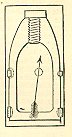 in pairs, so
as to fit the six grooves of the gun. For the
larger cannon-projectiles but three studs are
used, and these are cast on the projectile,
nearly opposite to its center of gravity; the
bearing sides of the studs are faced with white
metal to diminish friction against the grooves of
the bore. The shape of the grooves is such as to
center the projectile. The latter projectile is
used with increasing, the former with grooves of
uniform, twist. Russian, Austrian, and Spanish
artillery projectiles belong to this studded or
button class, but differ from each other in the
details of their construction. See
Compression-projectiles and Projectiles.
in pairs, so
as to fit the six grooves of the gun. For the
larger cannon-projectiles but three studs are
used, and these are cast on the projectile,
nearly opposite to its center of gravity; the
bearing sides of the studs are faced with white
metal to diminish friction against the grooves of
the bore. The shape of the grooves is such as to
center the projectile. The latter projectile is
used with increasing, the former with grooves of
uniform, twist. Russian, Austrian, and Spanish
artillery projectiles belong to this studded or
button class, but differ from each other in the
details of their construction. See
Compression-projectiles and Projectiles.
FRICTION PRIMER: A small brass or quill tube, known as the priming tube, filled with gunpowder and used to send a flame to the powder charge inside the bore. It was ignited by pulling an attached rough wire quickly through a friction composition contained in a second tube. The resulting flame was transferred through the tube and into the powder bag in the bore. A lanyard was used to pull the wire.
FULMINATE OF MERCURY : A chemical composition which exploded with great heat and violence when ignited. It was used in percussion caps, fuzes, and primers.
FUNNEL: A copper funnel used to pour bursting charges from the powder measure into the projectiles.
FURNACE: Constructed in forts or fortresses to heat shot for use as hot shot. A furnace could hold sixty shots at a time.
FUZE: Fuzes for projectiles may be classified as time-fuzes, percussion-fuzes, and combination-fuzes. The time-fuze serves to explode a projectile during flight, or at the end of a given period of time after its discharge from the gun. The percussion-fuze, rifled guns, serves to explode a projectile either during flight or on impact.
Time-fuzes – The time-fuze is composed of a column or ring of fuze-composition, driven or pressed into a suitable metal, wood, or paper case. The proportions of the composition vary according to the time it is intended to burn. The service time-fuzes comprise three varieties, viz., wooden-case mortar-fuzes, metal-case (Bormann) fuzes, and paper-case fuzes.
Fuzes for Mortar-shells – The hard, close-grained woods are best adapted for making fuzes; beech or ash is generally used. It should be dry, sound, free from sap, knots, worm-holes, or shakes. To turn the fuze-plug, a helper saws the plank into lengths equal to that of the fuze, and then into prisms, taking off the edges, and centering it on each end. The turner puts the fuze-plug thus roughed out in the lathe, turns its exterior, and graduates it, by means of a steel gauge, into inches and tenths of an inch, commencing at the bottom of the cup. When a number have been turned, the turner puts each fuze-plug into a chuck, bores it, and makes the cup with a tool for that purpose. The fuze-plugs should be carefully inspected, and verified with gauges, and those rejected which have splits, knots, or worm-holes, or which have not the proper dimensions. One turner can turn 500 fuze-plugs, or turn and bore 250, in ten hours.
The following utensils are required for driving the fuzes: driving-blocks, with holes of the size of the fuze-plug; benches; mallets for the 13-inch, 10-inch and 8-inch fuzes weighing 1 pound, for smaller fuzes weighing ½ to ¾ pounds; steel drifts, shod with copper, the shortest with a mark .2 inch from the end, copper ladles, to contain sufficient composition to make a height, when driven, equal to one diameter of the bore; copper pans; brushes.
The composition for 8- and 10-inch light mortar-fuzes is 2 parts of niter, 1 of sulphur, and 3 of mealed powder; for 10- and 13-inch heavy mortars, 2 of niter, 1 of sulphur, and 2 ¼ of mealed powder. The composition must be thoroughly ground and mixed with a muller, or in a leathern barrel with brass balls. The time of burning will vary according to the quality of the materials used (especially of the mealed powder) and the degree of their admixture. Trials should be made with each composition by driving several fuzes and getting their time of burning. There should not be any great variation in the times of burning of the different fuzes of the same composition. Fuze-composition should be prepared only a short time before being used, and should be preserved in close vessels in a dry place.
 When driving,
the workman is seated, his driving-block in front
of him, and a bench to hold a pan of composition
at his right hand. He takes a fuze, cleans it of
all foreign matter, inserting the drift to the
bottom of the bore. He then drops the fuze-plug
into the driving-hole, takes a ladleful of
composition, passing the drift along the edges of
the ladle to strike off the surplus; pours the
composition into the fuze-plug, strikes it two
gentle blows with the mallet, inserts the drift,
pressing it down on the composition, giving the
fuze two slight blows to settle the composition.
The workman strikes the drift twenty-one blows in
volleys of three, raising the mallet about one
foot each blow, and moving the drift after each
volley. He puts in another ladleful, and
continues as for the first. Care should be taken
to put in equal charges of composition each time,
and to give to each ladleful the same number of
blows and with the same force. Fuzes are often
driven by pressure in a screw-press.
When driving,
the workman is seated, his driving-block in front
of him, and a bench to hold a pan of composition
at his right hand. He takes a fuze, cleans it of
all foreign matter, inserting the drift to the
bottom of the bore. He then drops the fuze-plug
into the driving-hole, takes a ladleful of
composition, passing the drift along the edges of
the ladle to strike off the surplus; pours the
composition into the fuze-plug, strikes it two
gentle blows with the mallet, inserts the drift,
pressing it down on the composition, giving the
fuze two slight blows to settle the composition.
The workman strikes the drift twenty-one blows in
volleys of three, raising the mallet about one
foot each blow, and moving the drift after each
volley. He puts in another ladleful, and
continues as for the first. Care should be taken
to put in equal charges of composition each time,
and to give to each ladleful the same number of
blows and with the same force. Fuzes are often
driven by pressure in a screw-press.
Fuzes are all driven to the same height by means of a mark on the short drift, or the composition is bored out with the gouge to the same depth. They are primed with mealed powder for about .2 inch, driven with the same force as a ladleful of composition. The cup is filled with a paste of mealed powder and spirits of wine or strong whiskey, and laid aside to dry; it is then covered with a small piece of paper, over which is pasted a cap of strong, water-proof paper, marked with the number of seconds the fuze burns to the inch.
Time-fuze for Guns – This fuze consists of a paper case charged with fuze-composition; it is inserted, at the time of loading the gun, into a brass or wooden plug previously driven into the fuze hole of the shell. The following utensils are required for making the cases: pattern of wood, in the form of a rectangle joined to a trapezoid; iron former, .35 inch diameter; knife; glue-pot; brushes.
The paper is cut to the proper size by means of the pattern. The whole length of the strip must be determined by a trial for each kind of paper, to give the case the proper diameter. The strip is rolled hard on the former, beginning with the large end, and is glued after the first turn. When the case is dry, it is smoothed with a fine file or sand-paper.
The paper is cut to the proper size by means of the pattern. The whole length of the strip must be determined by a trial for each kind paper, to give the case the proper diameter. The strip is rolled hard on the former, beginning with the large end, and is glued after the first turn. When the case is dry, it is smoothed with a fine file or sand-paper.
There are different compositions used, one inch burning 2.5, 5, 10, 15, and 20 seconds respectively. Their time of burning is subject to considerable variation, according to the quality of the ingredients and the manipulation in mixing them; the exact proportions must be determined by experiment. The composition is carefully mixed, and several fuzes are first driven and their times of burning determined, and the proportions varied, if necessary, to produce the required result.
The following utensils are required for driving the fuzes: brass molds in two parts, which are held together by a wedge or cam; the molds have holes for four or five fuzes; steel drifts, .35 inch diameter; knife; mallet, weighing ½ pound.
The mold is put together and secured; the empty cases are inserted and driven gently in; their upper ends, projecting above the mold, are slit with a knife into four parts. The composition is put in and driven as described above, giving 15 blows to each ladleful, which will make .25 inch in length of the fuze. They are next primed by covering the larger ends with shellac varnish and dipping them into rifle-powder; when the priming has set, the entire fuze, except the priming, receives a coat of shellac varnish. The fuze is stained the proper color, according to the composition used, and the number of seconds that one inch will burn is marked on each fuze.
To cut the fuze it is inserted in an iron gauge, the bore of which is the same size and taper as the fuze, and its width is the true length of the fuze – 2 inches. The projecting ends of the fuze are first sawed off with a fine saw and then trimmed with a knife. They are packed in wooden blocks (poplar), bored to receive five fuzes each, and these blocks are wrapped in various-colored paper, to distinguish the different times of burning, having a printed label setting forth the kind of fuze, and place and date of manufacture, etc.
The fuzes are applied to projectiles by inserting them in wood or metal plugs, which are driven or screwed into the fuze-hole of the projectile. For sea-coast service, the paper-case time-fuze is inserted in a metallic plug fitting the projectile. The metallic plug is fitted with a screw-cap, called a water-cap, having a crooked passage, through which, by suitable priming, flame is communicated to the fuze, and the escaping gases are intended to exert sufficient pressure to prevent the entrance of water to extinguish the fuze, especially with spherical projectiles.
The insertion of the fuze in the rear end of the rifle-projectile has been proposed to dispense with the use of the water-cap, but the enormous force exerted upon the projectile, while in the gun, has been a serious obstacle to the practical use of a rear fuze.
Fuzes for Smooth-bore Field-guns and Mountain-howitzers – A fuze for shells and spherical case-shot for field and mountain service is that known as the "Bormann fuze." It consists of a circular disk of soft metal, containing an annular space charged with mealed powder. The outer circumference of the disk is chased with the threads of a screw to secure it in the shell. The annular space for the composition is concentric with the outer circumference, and connects at one end by a hole with a small magazine in the center of the disk, filled with rifle-powder, and closed on the under surface by a thin disk of tin. The fuze is charged from the under side by pressure, and a ring of the same metal is pressed firmly on the composition. The composition is thus securely protected from accidents, and the fuze is screwed into the shell in the laboratory. The metal covering the composition on top, being left thin, is easily cut with a knife or cutter at the moment of loading, and the composition exposed at the required point to the action of the flame. The graduations into seconds and quarter-seconds are marked on the upper surface of the disk. The time of burning of the whole length of fuze is 5 seconds.
The following utensils are required for casting the fuze: molds for the fuze; molds for the ring; hacksaw; nippers; mallet; kettle; ladle.
Melt the lead and tin together; heat the molds so as not to chill the metal is casting. Fill the mold with the melted metal, and tap it gently with the mallet to make the metal fill the small parts. Cut off the gate with the saw, and the ends of the ring with the nippers. It has been found convenient in opening and closing the molds to attach the two parts of the mold for the fuze and also for the ring to the jaws of a bench-vise, so that both molds are opened and closed by the same movement of the screw. The fuze-mold is kept hot by means of iron disks, which are heated and hung on the arbor which supports the molds. A mold of more approved pattern has been devised by which the casting is expedited.
The following utensils are required for charging the fuze: as strong screw-press; annular charger the size of the ring; annular drift; flat drift; round drift.
Take the mold in which the fuze was cast, place the fuze in the parts of the mold containing the screw and the upper or graduated side, and secure the mold by a ring driven on it. Draw up the piston, and fill the charger by pressing it into the mealed powder contained in a shallow pan; place the charger over the groove and force down the piston, transferring the powder into the fuze; insert the button in the magazine and the pin in the priming-hole to preserve their shapes; place the ring on the powder, and, with the annular drift, force it down by means of a strong screw-press, bringing the ring flush with the surface of the fuze; rivet the ring in its place with another drift; withdraw the button and the pin, charge the priming-hole with rifle-powder, and fill the magazine with musket-powder; cover the magazine with a disk of tin, and rivet it in place by means of, first, a flat drift, and then a round one, which turns down a part of the metal of the fuze over the disk. Remove the fuze from the mold, place it in a screw-chuck made to fit it, and turn off in a lathe the lower surface smooth and to the proper thickness. The powder of the fuze is now perfectly sealed up from the air. The fuze should be varnished.
The following table shows the principal dimensions and weights of the service-fuzes:
Dimensions and Weights of Fuzes |
Wooden Fuzes. |
Paper Fuzes. |
||
| 13 inch. | 10-inch. | 8-inch. | ||
| Whole length in inches. | 10.8 | 9.4 | 6.3 | 2 |
| Diameter………At top in inches. |
1.85 |
1.7 |
1.25 |
.53 |
| At bottom in inches. |
1.25 |
1 |
.9 |
.4
|
| Of bore in inches. |
.4 |
.3 |
.3
|
.35
|
| First cone…Length in inches. |
2.8 |
2.25 |
1.25 |
…….. |
Diameter at lower end in inches. |
1.65 |
1.55 |
1.15 |
…….. |
| Cup……….Depth in inches |
.6 |
.5 |
.4 |
…….. |
| Diameter….At top in inches. |
1.25 |
1 |
.75 |
……. |
| At bottom in inches. |
.9 |
.8 |
.6 |
…….. |
| Thickness of wood at bottom of fuze in inches. |
1.2 |
.9 |
.9 |
…….. |
| Length of composition in inches. |
9 |
8 |
5 |
2 |
| Drifts……..Diameter in inches. | .36 |
.27 |
.27 |
.3 |
| Length, exclusive of handle……First in inches. |
9 |
8 |
8 |
…….. |
| Second in inches. |
4.5 |
4 |
4 |
.. |
| Weight……Of composition for 100 fuzes in pounds |
8 |
4 |
2.5 |
2 |
| Of 100 fuzes complete in pounds |
54 |
33 |
16 |
…….. |
| Paper for the
case Whole length in inches |
…….. |
…….. |
…….. |
19 |
Length of rectangle in inches |
…….. |
…….. |
…….. |
6 |
| Width of rectangle in inches |
…….. |
…….. |
…….. |
2.25 |
| Width of small end in inches | …….. | …….. | …….. |
.4 |
Bormann Time Fuze. |
|
| Diameter of fuze, including threads | 1.64 inch. |
| Thickness | .45 inch. |
| Number of threads to the inches. | 12 |
| Diameter of plug, including threads | 1.07 inch. |
| Thickness for field-guns | 3 inch. |
| Number of threads to the inch | 12 |
Percussion-fuzes – Many varieties of fuzes have been used in service, under the names of percussion and concussion fuzes. Among the simpler ones, the Absterdam, Hotchkiss, Parrott, and Schenkl may be named. They are much alike in their general features. They consist of hollow metallic screw-plugs to fit the fuze-hole of the projectiles. A loosely fitting plunger is inserted in the bore of the plug, the front end of which is closed by a screw-plug or cap. On the forward end of the plunger a percussion-cap, or rather detonating device, is arranged, to be exploded and communicate fire to the bursting-charge, through an opening at the rear, by the plunger striking the plug or cap when the motion of the projectile is arrested. Various safety devices are used, having sufficient strength to prevent the plunger being thrown forward by shocks in transportation, etc., but weak enough to be broken by the shock of discharge, or impact of the projectile, as the case may be.
Combination-fuzes – Many varieties of combination-fuzes have been proposed and tested, but without satisfactory results. This variety of fuze would be best adapted to general service if perfected. If a perfect combination-fuze can be made, none other would be required, as it would have the properties of the other two, capable of use separately or combined. Granting certainty of ignition of the time element, only one kind of fuze would be required for all kinds of service. A good one should possess, in one structure, the properties of the most perfect time- and impact-fuzes. It should be simple in construction, safe to handle and transport, and easily applied to the projectile.
It is the opinion of many who have given the subject much study that no fulminate or friction composition should enter into its construction, except perhaps to insure the ignition of the time element of the combination. Certainty of ignition by the gases in the gun is not always attainable, especially with rifle-projectiles and breech-loading cannon which have but slight windage; therefore some form of inertia igniter is necessary. Such igniters are simple and easily made, and may be arranged for attachment to the fuze at the last moment before loading the gun, thereby avoiding all risk of accident in transportation, etc. The above conditions exclude all but a few of the devices subjected to trial, and the subject is still unsettled and under test. No one variety of the many offered for test has given sufficiently satisfactory results to warrant its adoption.
It is impossible that any species of fuze should be absolutely perfect. When suitable opportunities for observation occur, it is noticed that in firing a number of shells many do not explode. the failure of the composition to ignite is probably generally due to the absorption of moisture; and therefore all fuzes which have been more than one year in service should be returned to the laboratory. Fuzes of over two years’ date of manufacture should not be issued for service. Sometimes the fuze is extinguished after having been ignited. This may occur when the shell ricochets on soil or water. Water is not so detrimental as sand, and the fuze is rarely extinguished by several ricochets upon it. Generally the gases evolved by the combustion of the composition will repel with great energy any obtrusive matter which would extinguish the fuze if once in contact with the ignited surface.
Premature explosions may be caused by the increase of the ignited surface of the composition resulting from cracks in the case or composition itself, or by interstices between the case and composition; and in proportion to the extent of this cause so will be the increased celerity of the combustion. Crevices may occur in the composition from some defect in the tools or in the mode of using them, or they may be created by bending the case. It may also happen that the displacement of the shell by the charge of the gun will force in the column of composition or the case with it. This would of course cause the shell to explode very quickly. The shell may be defective in thickness or quality of metal, and be crushed by the force of the discharge, when the explosion will take place in or near the gun. The bursting of the shell near the muzzle of the gun is sometimes attributed to the detonating qualities of the powder in the shell. It is manifest that the premature explosion of shells is far more detrimental to their efficiency than the failure to be exploded at all. See Absterdam Percussion-fuze, Bormann Fuze, Boxer-fuze, Concussion-fuze, Percussion-fuze, Electric Fuzes, Fire-works, Hotchkiss Percussion-fuze, McIntire Fuzes, Mortar-fuze, Schenkl Percussion-fuze, Seacoast-fuze, Splingard Fuze.
FUZE-AUGER: An instrument for regulating the time of burning of a fuze by removing a certain portion of the composition. It consists of a steel bit, fastened into a wooden handle, at the lower end of which is a brass socket, with a bar, under which a graduated limb of the slider moves. The bit fits into the slider, and is by a steel thumb-screw fastened to it in any required position. The position of the slider, which determines the depth to which the auger bores, is regulated by a fine scale attached to it by a screw.
FUZE-BLOCK: A simple contrivance for holding paper time-fuzes when being cut. It consists of two blocks of wood hinged together so as to open and shut after the manner of a book. In each end is a recess into which the fuze is placed, and where it is securely held by pressing the blocks tightly together. The fuze is put in with the small end extending out of the end of the block, the point at which it is to be cut being even with the end of the block. Along one side of the recess is attached the brass scale. This was intended for fuzes of obsolete pattern. As now made, each fuze is divided into as many equal parts as the number of seconds for which its entire length (two inches) is intended to burn. These parts are marked, and are, the guides in cutting the fuze; the latter operation being performed with the fuze-knife, which is a very sharp and thin-bladed knife (preferably a shoe-knife), or a fine saw.
FUZE-EXTRACTOR: An implement used for extracting wooden fuzes from the fuze-hole, when they have been too firmly driven to be withdrawn by the shell plug-screw, or in any other way. It consists of an inner screw and stem of steel, riveted to an iron handle, and contained in a hollow steel screw, which works up and down by means of an iron nut with two handles. The hollow screw is prevented from turning by a slot and a feather in the frame, which is of brass. The nut is kept in place by four iron set-screws, the points of which enter into a groove in the nut. To extract a fuze, the bottom of the frame is placed on the shell over the fuze-head, and the inner screw screwed into the fuze by means of the upper handle. The handles of the nut are then turned, which raises the hollow screw, and with it the inner screw and the fuze.
FUZE-HOLE: The hole in a shell prepared for the reception of the fuze-stock. The loss of force by the fuze-hole may be ascertained with sufficient accuracy, provided we know from an actual experiment the amount of the loss from the fuze-hole of any one shell.
Let R and r be the exterior and interior radii
of a spherical projectile; T, the tenacity of the
metal; I, the radius of the fuze-hole; w’,
the weight of powder necessary to burst it under
the supposition that there is no loss of force at
the fuze-hole; w, the weight of powder that is
actually required to burst it.
![]() By formulas
approved we obtain the value of w’; w –
w’ is therefore the amount of loss from the
fuze-hole. Take another projectile, and let
w’, represent the charge which is necessary
to burst it, under the supposition that there is
no loss, and w, the weight that is found by
experiment necessary to burst it; w, - w’
will represent the loss. We are at liberty to
suppose the loss from the two fuze-holes is
proportional to the size of the holes, and the
density of the gases at the moment of rupture; we
shall therefore have this proportion:
By formulas
approved we obtain the value of w’; w –
w’ is therefore the amount of loss from the
fuze-hole. Take another projectile, and let
w’, represent the charge which is necessary
to burst it, under the supposition that there is
no loss, and w, the weight that is found by
experiment necessary to burst it; w, - w’
will represent the loss. We are at liberty to
suppose the loss from the two fuze-holes is
proportional to the size of the holes, and the
density of the gases at the moment of rupture; we
shall therefore have this proportion:
From the experiments made at Metz in 1835, it was shown that this mode of estimating the loss of force by the fuze-hole was sufficiently accurate for practical purposes. See Bouching and Shells.
FUZE-MALLET: An implement for setting the fuze home. It is cylindrical in shape, with a handle on one end, and is turned out of a single piece of dogwood, oak, or other hard wood.
FUZE-PLUG: Fuze plugs are made of brass or of
close-grained wood, well seasoned.
 They are
turned to a size a little larger than the
fuze-hole, but of the same taper, - 2.5 inches
long; a hole is bored through the axis and reamed
out to receive the paper fuze, and the large end
is counter-bored and tapped to receive the
water-cap. If a wooden plug be used, a short,
hollow cylinder of brass, .5 inch long, .15 inch
thick, is inserted in the recess before the plug
is driven, and afterwards tapped to receive the
water-cap.
They are
turned to a size a little larger than the
fuze-hole, but of the same taper, - 2.5 inches
long; a hole is bored through the axis and reamed
out to receive the paper fuze, and the large end
is counter-bored and tapped to receive the
water-cap. If a wooden plug be used, a short,
hollow cylinder of brass, .5 inch long, .15 inch
thick, is inserted in the recess before the plug
is driven, and afterwards tapped to receive the
water-cap.
The water-cap, shown in the drawing, is a plug of brass, .5 inch long, .6 inch in diameter, chased with 12 threads to the inch. One end has a shallow recess cut in it, .1 inch deep, larger at bottom than at top; a hole .1 inch in diameter is bored through the middle of the cap, and a hole is bored from either end into this transverse hole, but meeting it at points .25 inch or more apart; these and the recess in the end are filled with mealed-powder paste. Diameter of hole at bottom of recess, .53 inch; at small end, .4 inch.
A little shellac is brushed around the safety-plug and lower end of fuze-plug; also around the leaden patch and top of stock. A pasteboard cap is put on over the safety-plug end of the fuze-plug to prevent the plug from being broken off, and the fuzes thus prepared are stowed in boxes. See Fuze and Water-cap.
FUZE REAMER: The implement used to enlarge the hole in a fuze-plug so as to make it of the proper size for the paper fuze.
FUZE SETTER: An implement for setting wooden fuzes in the fuze-hole. It is made of brass; the bottom is countersunk and cup-shaped, to prevent it from slipping off from the head of the fuze.
FUZE-WRENCH: A three pronged wrench used for setting fuze-plugs that are to be screwed into the shell. One prong contains forks for the fuze-plug, and another one smaller forks for the water-cap.
FUZE: The device employed in a shell for the purpose of igniting the bursting charge and causing the shell to explode. Fuzes were classified in four categories: time, percussion, combination, and concussion. Metal fuzes were threaded and screwed into the fuze hole while paper fuzes were tapered and driven by a hammer into a wooden fuze plug or adapter.
FUZE ADAPTER: See Fuze Plug.
FUZE AUGER: A tool used to reduce the length of the powder composition column in a paper time fuze after it had been set in the projectile. The auger consisted of a bit which fit inside a graduated slider scale. The bit was set to the appropriate depth according to the slider. The auger then forced the bit into the fuze and removed the powder.
FUZE BLOCK: See Fuze Measure.
FUZE CUTTER: Also known as fuze punch or fuze gouge. A steel chisel, with a brass or wooden handle designed for cutting into the powder train in a Bormann time fuze.
FUZE ENGINE: See Fuze Extractor.
FUZE EXTRACTOR: Also known to artillerists as a Fuze Engine. It was used to remove fuzes from the wooden fuze holders when they had been driven in too far. The inner screw and its stem were made of steel and riveted into the iron handle. The stem was contained in a hollow screw of steel which was worked up and down by means of an iron nut with two handles. The bottom of the frame was placed over the fuze head and the inner screw was twisted into the fuze by means of the upper handle. The handles of the nut were then turned and the screw bit into the fuze and twisted it out.
FUZE GOUGE: See Fuze Cutter.
FUZE HOLDER: See Fuze Plug.
FUZE HOLE: A circular opening manufactured into spherical and elongated shells to admit a fuze, fuze plug, or fuze holder. Fuze holes were threaded or smooth depending on the type fuze intended for the shell.
FUZE IMPLEMENT: Nomenclature given to tools used to prepare and set the fuze systems for artillery projectiles. The included the Fuze Auger, Fuze Cutter (Punch), Fuze Extractor, Fuze Mallet, Fuze Measure, Fuze Reamer, Fuze Saw, Fuze Setter, and Fuze Wrench.
FUZE MALLET: A wooden hammer made of one solid piece of dogwood or oak. It was used to drive fuzes and fuze plugs into projectiles.
FUZE MEASURE: Also known as a Fuze Block. A wooden block or board with graduated scales used to measure the length of various paper time fuzes.
FUZE PLUG: Sometimes called a fuze adapter or fuze holder. A metal or wood device that was set into the fuze hole to hold a paper time fuze. Metal fuze plugs were made of brass, copper, lead, or pewter and screwed into the hole. Wooden fuze holders were driven by a fuze mallet into the hole. The wooden fuze plug was tapered to cause a close seal.
FUZE PUNCH: See Fuze Cutter.
FUZE REAMER: An implement used to enlarge the hole in a fuze plug for proper fitting of the plug.
FUZE SAW: A small saw, with a 10-inch iron blade, used to cut wooden fuzes to the desired length.
FUZE SETTER: A brass cylinder 5- to 6-inches in length and 2-inches in diameter. It was used to seat a wooden fuze holder into the fuze hole of a shell.