Sylvanus Sawyer Patent # 13,799
Addison M. Sawyer Patent # 33,754
Sylvanus Sawyer Patent # 34,040
Sylvanus Sawyer and Addison M. Sawyer Patent # 36,172
Addison M. Sawyer Patent # 38,699
Sawyer Combination Fuze
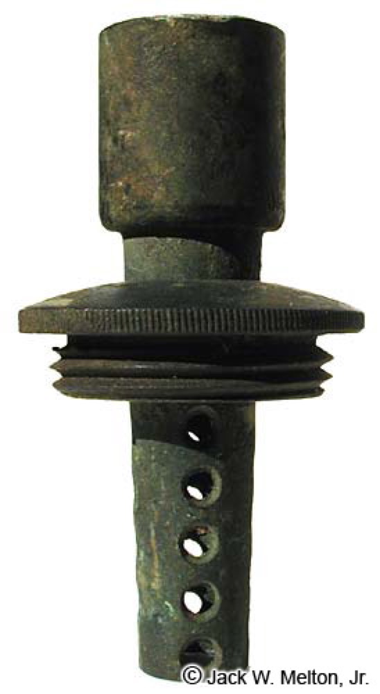
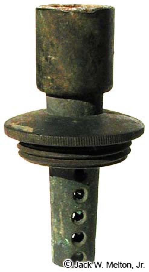
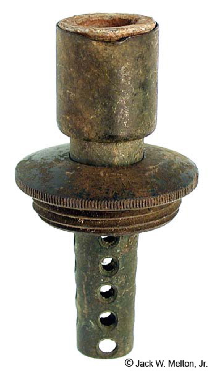

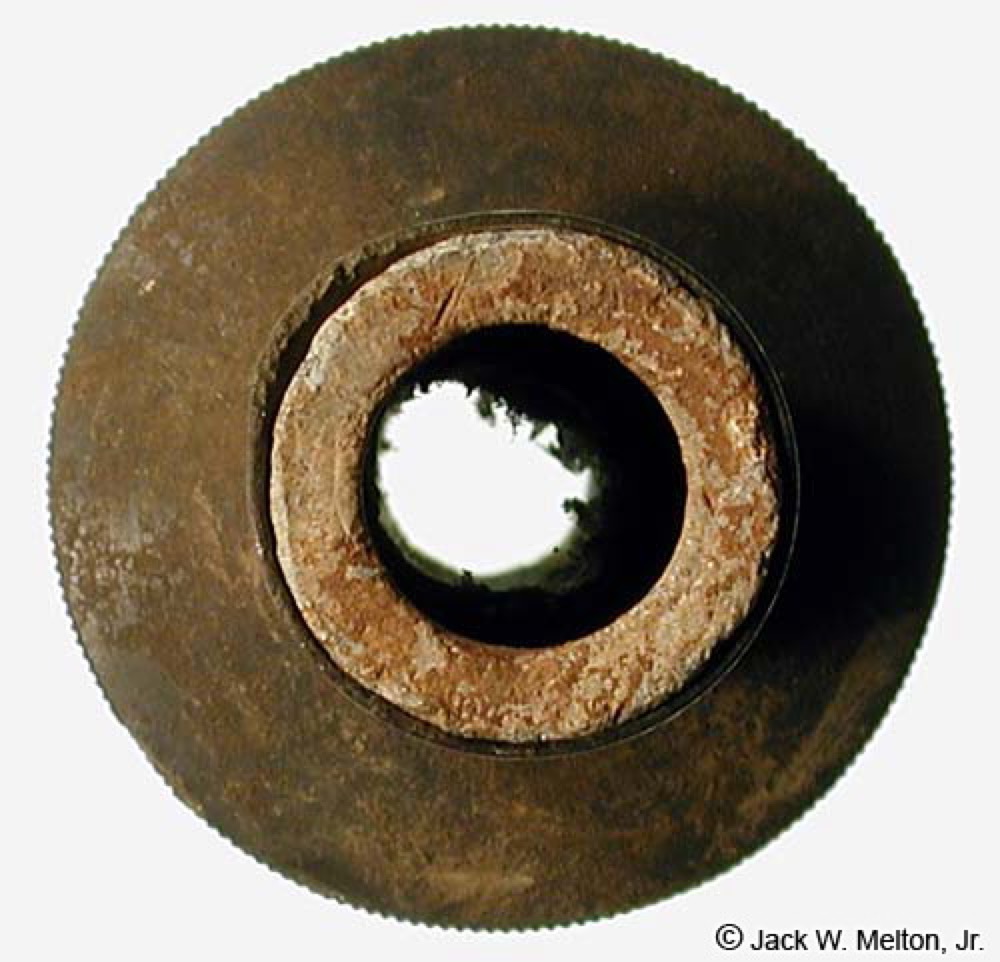
12 Threads per inch
1/4, 1/2, and 3/4
seconds
2.87-inches long
with 2 to 7 second
settings
UNITED STATES PATENT OFFICE.
_________________
S. SAWYER, OF FITCHBURG, MASSACHUSETTS.
IMPROVED COMPOUND PROJECTILE.
________________
Specification forming part of Letters
Patent No. 13,799, dated November 12, 1855.
_________________
To all whom it may concern:
Be it known that I, SYLVANUS SAWYER, of Fitchburg, in the country of Worcester and State of Massachusetts, have invented an Improved Bomb-Shell; and I do hereby declare that the same is fully described and represented in the following specification and the accompanying drawings, in which -
Figure 1 denotes a side elevation of the same; Fig. 2, a top view of it; Fig. 3, a bottom view of it. Fig. 4 is a central and longitudinal section of it; Fig. 5, a transverse and horizontal section of it.
The said projectile is intended to be discharged from a cannon or howitzer provided with helical grooves in its bore essentially like those in a rifle, the projectile being made with wings or guides to enter such grooves, and so far therein that during the discharge of the piece the grooves may impart to the shell a whirling or rotary motion on its axis, which shall be maintained during its flight or course toward the object to which it may be directed.
In applying to the external surface of conical or cylindro-conical shells lead, when such shells have been made of cast-iron, it has been customary to cast the lead on the cylindrical surface of the shell, or that part of it which during its passage through the bore of the gun would be likely to rub against the same, the lead or soft metal having been applied as a protection to the gun, or as a means of not only preventing that wear or tear of it which would result were the iron surface of the shell to be allowed to come in contact with the inside surface of the bore, but the bursting of the gun, which is liable to follow from the choking of it by the shell, where such friction or tearing of the bore is produced. Under these circumstances it has been found that, owing to the rapid passage of flame over the surface of the lead during the movement of the shell through the bore, such lead will be instantaneously ripped or melted off the shell, and consequently rendered useless for the purpose for which it was applied thereto. I have endeavored to make a shell in such manner as to stop the passage of the flame by it, or prevent it from tearing or melting off the anti-friction metal. For this purpose I so construct the shell and apply the anti-friction metal thereto that the force of the explosion, acting in conjunction with the hard metal at the butt or rear end of the shell, shall expand a portion of such anti-friction metal, so as to press it firmly against the inner surface of the bore of the piece and cut off the passage of the flame by the shell or its leaden or anti-friction coating. Furthermore, in order to fasten the anti-friction metal firmly to the cast-iron shell or body, I first coat the latter with tin, or some metal which will have a stronger affinity for the cast-iron and the lead or anti-friction metal than the latter has for the iron. This done, I cast on and around the metallic coating so applied the coating or case of lead or anti-friction metal. I also form the rear part of the iron case or shell frusto-conical or tapering, and apply to such an extra thickness of anti-friction metal, which, when an explosion of the charge of the gun takes place, shall force or crowd the surplus anti-friction metal up the conical or tapering surface joining the cylindrical body of the shell, the said surface serving to expand the ring of metal on it, and cause it to fit closely to the bore of the gun, and so as to prevent windage, and the passage of flame by such ring to such extent as to tear or melt the anti-friction metal in advance of the ring. Besides the above, I extend the anti-friction metal beyond and around the screw-plug of the shell, and screw into it the explosive cap of the shell, arranging such cap directly over the screw-plug, and so that when the shell is thrown against an obstacle point first its momentum shall compress the anti-friction or soft metal, so as to cause it to give way and let the explosive cap with force down, so as to compress the percussion wafer or priming arranged on the top of the screw-plug or in the explosive cap, as the case may be.
In the drawings, A. shows the cast-iron hollow body of the shell, which, when the projectile is used, is to be charged or loaded with powder or other proper material, such body, generally speaking, being formed cylindro-conical, and provided with a screw-plug, B, and a series of helical wings, E E E E E E, arranged as seen in the several figures.
C exhibits the covering of tin, while D shows the coating of lead oranti-friction metal, it being extended up above and around the screw-plug B, and provided with a female screw, as seen at d d in Figs. 1, 2, and 4, such screw serving to receive a male screw, e e, formed on the explosive cap F. The said cap F constitutes a cover to the screw-plug B, which is provided with one or more vent-holes, f f, leading down through it. Above the top of the said plug, and between it and the cap F, or in the latter, the percussion priming or wafer is to be placed. Under all ordinary circumstances the compressible anti-friction metal sustaining the screw-cap F will retain it from being forced down upon the priming, the cap being formed with a shoulder, h h, to rest on the metal. When the shell is forced from the gun, the cap first comes in contact with the object fired at and by such and the force or momentum of its flight will be driven down, so as to compress the percussion-priming and to cause an explosion of it, the holding metal yielding under the force of the impingement of the shell and suffering the explosive cap to so act. The wings E, as well as the body of the shell, are to be coated with the tin and anti-friction metal, which should also extend over the butt or rear end of the shell and its tapering part a a, as seen at b b in Fig. 3.
Previous to inserting the shell in the piece of ordnance a patch or cloth hood or bag may be drawn over it, partially or wholly, so as to separate its sides from the inside surface of the bore. A shell constructed on the above plan has been found exceedingly effective in preventing friction and wear of the gun and the consequent choking and bursting of it which might ensue, besides being of great advantage so far as saving of ammunition is concerned.
At b b, Fig. 4, I have exhibited the annulus of lead or soft metal extending around the tapering or conical part a a of the cast-iron body of the shell. When the explosion of the charge of the gun takes place, this annulus will be driven up the tapering part a a and expanded thereby, and so as to produce effects as stated.
I claim -
1. Combining with the butt or flat rear end of the cylindro-conical iron shell a layer of lead or softer metal than that of which the body of the shell is composed, and united or not to a layer of such metal extended around the sides of the shell, as described, the same operating in manner as specified while the shell is being projected through the bore of a gun by a discharge of the powder therein.
2. Making the rear part of the shell tapering or conical, as seen at a a, combining therewith a ring or annulus b b, of lead or its equivalent, the same being substantially in manner and for the purpose as hereinbefore specified.
3. Confining the explosive screw-cap to the body of the shell by means of a softer or yielding metal or casing, which, when the cap or shell shall strike an object, shall give way under the force of the blow and let the cap down with force, so as to compress the percussion wafer or priming in it or on the main screw, stopper, or plug, and so as to create an explosion thereof, as stated.
In testimony whereof I have hereunto set my signature this 9th day of October, A. D. 1855.
SYLVANUS SAWYER.
Witnesses:
R. H. EDDY,
F. P. HALE, Jr.
UNITED STATES PATENT OFFICE.
____________________
ADDISON M. SAWYER, OF FITCHBURG,
MASSACHUSETTS.
____________________
IMPROVEMENT IN CANISTER-SHOT FOR ORDNANCE
____________________
Specification forming part of Letters
Patent No. 33,754, dated November 19, 1861.
____________________
To all whom it may concern:
Be it known that I, ADDISON M. SAWYER, of Fitchburg, in the county of Worcester and State of Massachusetts, have invented an Improved Canister-Shot, of which the following is a full, clear, and exact description, reference being had to the accompanying drawings, making part of this specification, in which -
Figure 1 is a perspective view of my shot; Fig. 2, a longitudinal section through the same after it is charged and ready for use.
My invention has for its object to produce a canister-shot that may be fired from a rifled cannon without injury to the grooves, and that will carry the shot in a comparatively compact body, and then scatter them in a cone diverging in front of the troops at which they are fired. The ordinary canister-shot is liable to several objections: first, the balls are apt to be forced down to the rear end of the canister at the instant of discharge, by which the metallic canister is driven into the grooves of the gun, which are thereby destroyed; second, when thus wedged into the tail end of the shot, they burst the canister and fly wild the instant they leave the gun; third, if the canister were of sufficient rigidity to resist being forced into the grooves of the gun, the balls would be wedged into its tail end, and this end thus becoming the heaviest would prevent the canister from flying mouth foremost.
My present invention consists in the employment of a rigid canister of such strength that it shall neither be crushed by the discharge of the piece nor be forced out into the grooves of a rifled gun. This I accomplish by making a canister of sufficient strength to resist both of these forces; and to prevent the balls from wedging into the tail end of the canister and remaining there, I open one or more holes in its rear end, through which sufficient force is communicated by the discharge to state the balls simultaneously with the canister and to drive them to its forward end, so that at the moment when the projectile is leaving the gun its forward end is much heavier than its rear, and the consequence is that the canister flies mouth foremost and the balls being discharged while it is in this position are all projected in lines having only a moderate divergence from the line of flight of the canister.
To enable others skilled in the art to understand my invention, I will proceed to describe the manner in which I have carried it out.
In the said drawings, A is the canister, which is to be of cast-iron or other suitable material, and of sufficient strength to resist the crushing of its sides by the force of the discharge. Through the rear end of the canister I make three holes, f, and to the forward end or mouth I apply a cover, B, of tin or of other suitable material that will keep the balls in place. This cover has a flange, g, and is held in its place by punching from the inside into the holes I, it being simply necessary to hold the cover on with sufficient force to prevent the balls from dropping out during transportation and loading.
To charge the canister a layer of paper, C, is first placed at the bottom, and upon this a layer of balls, D, next a layer of shavings, F, or other suitable substance to prevent the balls from coming in contact with each other, and then alternately balls and shavings until the canister is filled. The contents are secured in place, as before stated, by the cover B. Either leaden or other balls may be used, those of lead being preferred. When the projectile is discharged from the gun, a portion of the force of the discharge entering by the holes f compresses the contents of the canister so as to throw the balls to its forward end, and the canister is thus caused to move mouth foremost; and as the canister leaves the gun, or very shortly after its escape therefrom, the expansion of the gas which has entered behind the paper C assists to free the canister of its balls, which are discharged in line nearly parallel to the line of flight.
What I claim as my invention, and desire to secure by Letter Patent, is -
A canister-shot, constructed in the manner substantially as described.
ADDISON M. SAWYER.
Witnesses:
JOSEPH E. MANNING,
HENRY A. GOODRICH.
UNITED STATES PATENT OFFICE.
______________
SYLVANUS SAWYER, OF FITCHBURG,
MASSACHUSETTS.
___________________
IMPROVED FUSE-HOOD FOR SHELLS.
___________________
Specifications forming part of Letters
Patent No. 34,040, dated December 24, 1861.
___________________
To all whom it may concern:
Be it known that I, SYLVANUS SAWYER, of Fitchburg, in the county of Worcester and State of Massachusetts, have invented a new and useful device to be applied to the fuses for igniting shells, which I denominate a "Fuse-Hood;" and I do hereby declare that the following is a full, clear, and exact description of the construction and operation of the same, taken in connection with the accompanying drawings, making part of this specification, in which -
Figure 1 is an elevation and Fig. 2 a section, of the same, showing its application to the projectile patented by me November 13, 1855, fitted with the "combination fuse," so called. Fig. 3 represents the application of the "hood" to the common metallic fuse-stock of a spherical shell. Fig. 4 represents the application of the hood to the common wooden fuse-stock in a spherical shell; and Figs. 5, 6, and 7, plans of the inside of the hood, showing the different forms of attachment to the different fuse-stocks before referred to.
The subject-matter of my invention consists of a new device which is designed to be applied to the fuses of shells where the fuse is ignited by the fire of the charge of the gun, and more particularly to shells for rifled cannon, where there is but little or no windage allowed to the projectile, in which case the fuse must be ignited by the flame after it leaves the muzzle of the gun. The device consists of a thin circular concave plate or disk placed concentric with and at a little distance from the outer extremity of the fuse, as is shown in the drawings, and is supported in that position by any convenient attachment to the fuse-stock. Its purpose is to deflect or conduct a part of the flame in which the projectile is enveloped after it leaves the muzzle of the gun, directly upon the fuse to insure its ignition. It has been found by experience that where there is no windage to the projectile the ignition of the fuse will rarely take place unless some device of the nature of the hood is employed.
In the drawings, A represents the hood, made of thin brass or other metal of the form shown, and is placed over the fuse and is held in that position by any convenient arrangement that will leave a free space between it and the fuse.
B is the fuse-stock.
C is the fuse-case, which contains the fuse-powder D.
E, Fig. 5, represents three clasps, of thin plate metal, attached to the hood, by which it is fixed to the fuse-stock of the combination-fuse, as in Fig. 2.
F, Fig. 6, represents two short triangular studs attached to the hood, designed to be driven into the wrench-holes in the common metallic fuse-stock, as in Fig. 3.
G, Fig. 7, represents three nails or points attached to the hood, designed to be driven into the common wooden fuse-stock, as shown in Fig. 4.
These several forms of applying the hood to fuses of different kinds will sufficiently explain its use without further description.
What I claim as my invention, and desire to secure by Letters Patent, is -
The employment of a hood or other equivalent device, in combination with a fuse, substantially in the manner and for the purpose described.
October 10, 1861.
SYLVANUS SAWYER.
Witnesses:
WM. C. HUBBARD,
W. ST. C. REDMAN.
UNITED STATES PATENT OFFICE.
SYLVANUS SAWYER AND A. M. SAWYER, OF FITCHBURG, MASSACHUSETTS.
IMPROVEMENT IN COMBINED TIME AND PERCUSSION FUSES
FOR EXPLOSIVE SHELLS.
_______________________
Specification forming part of Letters Patent No. 36,172, dated August 12, 1862.
To all whom it may concern:
Be it known that we, SYLVANUS SAWYER and ADDISON M. SAWYER, of Fitchburg, in the county of Worcester and State of Massachusetts, have invented a new and useful Improvement in Fuses, which we style a "Combination-Fuse;" and we do hereby declare that the following is a full, clear, and exact description of the nature and operation of our invention, taken in connection with the accompanying drawings, making part of this specification, in which -
Figure 1 represents in section one form of our combination-fuse as applied to the projectile patented to Sylvanus Sawyer, November 13, 1855. Fig. 2 is a plan of the same. Fig. 3 represents another form of the combination-fuse applied to an iron
cylindro-conical shell, and Fig. 4 is plan of the same. Fig. 5 represents another form of the combination-fuse applied to the before-mentioned projectile of S. Sawyer, having the time-fuse of the kind known as the
"Bormann fuse." Fig. 6 is a plan, and Fig. 7 a horizontal section on the line X of Fig. 5 of the metallic
fuse-case for the same.
The subject-matter of our invention relates to the construction of fuses to be used for exploding shells, or for any other equivalent purpose, but is more particularly adapted to shells or projectiles used in rifled cannon; and it consists in combining in one
fuse-stock both a "time-fuse," so called, or a fuse which is ignited by the fire of the gun and burns for a definite length of time before igniting the charge in the shell, and a percussion
fuse or cap which is ignited by its striking against any hard body, so that the explosion of the shell may be made to take place either before or after striking. The time-fuse employed in combination may be of any of the well-known forms, and filled with any suitable burning composition or charge, and the representation of three forms of
fuse in the drawings is simply for the purpose of explaining the principle and several of the modes in which we have contemplated the application of that principle or character which distinguishes it from other inventions as applied to each of three well-known kinds of time-fuse and to two well-known kinds of shell, one of which is coated with a soft metal and the other not, which are examples of the application of the invention to both these conditions, and they also exemplify the nature of the modifications which are necessary in applying the fulminating or percussion cap or
fuse to each form. The fuse-stock also, being made externally of the usual form in the part that connects it with the shell, can be applied in place of the
fuses ordinarily used without any modification either in the manner of constructing the shell or of loading it.
In the drawings, A represents the iron shell, and B the lead covering of the shell. (Shown in Figs. 1 and 5.) C is the
fuse-stock. D is the fuse-case. E is the fuse-powder. F is the fulminating-powder. G is the striking-surface, against which the fulminating-powder is driven to explode it. In Figs. 1 and 3 the
fuse-powder is placed in a cylindrical paper case, D, in the usual way; but in Fig. 5 the
fuse-powder is placed in a spiral channel in the leaden case D, which is fitted in a recess in the
fuse-stock C. Between the contiguous surfaces of the case D and stock C is placed a thin layer of cork, K, which is pressed between them, and serves to prevent the fire from passing across the partitions between the convolutions of the channel, and insures its burning only in the direction of the convolutions to the central orifice
c, through which, and also through the holes d in the plug G, the fire passes to the bursting-charge. The outside of the
fuse-case is shown in Fig. 6, and is provided with marks and figures opposite to the channel to indicate the point at which a hole is to be cut through the case to the powder to give the proper length of
fuse to burn the time required. It is a modification in form of the
Bormann fuse, and acts in the same manner. The fire from the fulminating-water F also passes through the holes d in the plug G to the charge in Fig. 5, and through the space
d between the fuse-stock C and plug G in Fig. 1, and through the hole
d at the inner end of the fuse-stock; C in Fig. 3, in a perfectly obvious manner. In the combination of the fulminating-fuse with each of the forms of time-fuse mentioned the principle is the same. The surfaces which explode the fulminating wafer or
fuse are held asunder by some agency that will yield to the force of the blow when the
fuse strikes a hard body at a high velocity, but will not yield to any ordinary blow that it might accidentally receive. This is provided for in Figs. 1 and 5 by the upsetting of the lead B, as is described in S. Sawyer's patent before mentioned, and in Fig. 3 by driving the wooden
fuse-plug H, which carries the fulminating-fuse F into its tapering socket, so as to explode it against the surface G. This principle may obviously be applied in a great variety of forms; but the three represented will show the general character of the combination, and the mode of applying it to the different kinds of
fuses and different kinds of projectiles analogous to those represented.
We are aware that a time-fuse and a percussion-fuse have both been used in connection with one shell, as is seen in an English patent granted to Wm. G. Armstrong, April 10, 1858, and therefore do not broadly claim such employment of the two
fuses.
What we claim as our invention, and desire to secure by Letters Patent, is -
The combination, in one fuse-stock, of a percussion-fuse with a time-fuse, substantially as described.
October 12, 1861
SYLVANUS SAWYER.
A. M. SAWYER.
Witnesses:
WM. C. HUBBARD,
W. ST. C. REDMAN.

UNITED STATES PATENT OFFICE
__________________
Addison M. Sawyer, of Fitchburg, Massachusetts.
IMPROVEMENT IN IGNITING TIME-FUSES OF SHELLS
__________________
Specification forming part of Letters Patent No. 38,699. dated May 26, 1863.
__________________
To all whom it may concern:
Be it known that I; ADDISON M. SAWYER, of Fitchburg, in the county of Worcester and State of Massachusetts, have invented a new and useful Improvement in Fuzes for Igniting Ordnance Shells; and I do hereby declare that the following is a full, clear, and exact description of the construction and operation thereof, taken in connection with the accompanying drawings, making a part of this specification, in which -
Figure 1 represents in elevation the fuse applied to a cylindro-conical "Sawyer's" shell. Fig. 2 represents the same in section. Fig. 3 represents the fuse-stock in plan. Fig. 4 represents the fulminating - primer in plan, and Fig. 5 a vertical section of the same.
The subject-matter of my invention relates to the manner of constructing and applying a detonating-primer for igniting a time-fuse in an ordnance shell, so that the fuse shall be ignited at the instant of the explosion of the gun by the shock of the discharge, and is designed more particularly to be used in rifled guns where, from the absence of windage, the fuse cannot well be lighted by the flame that escapes past the shell in the gun.
My invention consists, in the first place, in constructing upon the exterior part of the fuse-stock, and immediately adjacent to the time-fuse, an open socket, or its equivalent, for holding a detonating-primer to ignite the time-fuse, which is actuated by the joint action of its own inertia and the first impulse of the discharge of the projectile, the construction of the socket, and primer, respectively, being such that the primer may be placed in the socket at the time of placing the shell in the gun, and thus avoid all risk of accidental explosion, which might occur if the primers were carried in the fuse-stock, as is the case with all fuses of which I have any knowledge, heretofore constructed, in which the time-fuse was lighted by a fulminating-primer.
My invention also consists in the manner of constructing the primer and of holding it in its socket, so that it shall not be either accidentally displaced or ignited, and, also, so that it shall not obstruct the free burning of the time-fuse, nor fire the shell in the gun by the direction action of the fulminating powder of the primer, as will be hereinafter explained.
A is the fuse-stock. It is of the form known as the "combination-fuse," or a fuse-stock containing both a time-fuse and a percussion-fuse.
B is the cast-iron body of a "Sawyer" shell, so called, and C is its soft-metal covering.
D is the plug, which acts as a striker for exploding the fulminating-powder E, placed in the cap of the fuse-stock, as shown, and operates in the same manner as is described in the patent of Sylvanus Sawyer, dated November 13, 1855.
K is the time-fuse case, inserted in the fuse-stock in the usual manner, and L the fuse-powder.
M is a small cylindrical socket upon the exterior of the fuse-stock, to receive the fulminating-primer. H, for igniting the time-fuse. The outer or forward part of the socket is slightly beveled upon the inside, at F, to receive the corresponding beveled part of the primer, as is shown more clearly at F in Fig. 5. The socket M, just within the beveled part, is made of a larger diameter, so that when the beveled part F of the primer has been forced past the stricture of the socket it will move freely. The primer is made of an annular form, as seen in Fig. 4, of brass and lead, as shown in the drawings, the brass part having an annular recess at I for holding the fulminating-powder, the lead being cast upon it, both to give it more weight within small compass, and also because of its malleability, to enable the projecting beveled part F to be compressed and pass through the stricture of the socket M, as before stated. The slight inclination of the beveled surfaces of the socket and primer, where they come in contact, enables the primer to become fixed in the socket by merely pressing the primer into it. The shells are intended to be carried into the field loaded and with their fuses in place; but the primers are to be carried by the gunners, and placed in the socket after the shell is placed in the muzzle of the gun, before ramming it home, so that all possible accident from the explosion of the shell by the premature ignition of the primer is prevented. When the gun is fired, the fuse-stock, being driven forward with the shell by a sudden impulse, is, by the inertia of the primer, driven past it, and brings the fulminating-powder in the recess T in contact with the annular projection G on the fuse-stock and around the exposed end of the time-fuse, which ignited it with certainty. The central opening through the primer permits the flame from the fuse to escape freely, and also permits the escape of the explosive gases from the fulminating-powder of the primer, which otherwise might drive the fuse into the shell and explode it in the gun.
Although I have described and represented the socket for holding the primer as a hollow cylinder, with the primer inserted within it, I do not wish to confine myself merely to this form, as it may be variously modified and still embrace the same principles - as, for instance, the primer may be placed upon the outside of the socket in a manner similar to the percussion cap of a musket - and other modifications of a like nature may be made, and still retain the essential characteristics of my invention - which are, first, that the socket or receptacle for the primer shall be open or exposed, so that the primer may be placed and confined in or upon it without any mechanical adjustment; second, that the striking-surfaces which explode the fulminating-powder of the primer shall be kept asunder until the discharge of the gun; and, third, that the gases from the burning of both the fuse and the primer shall have free escape. I am aware that it has been proposed to ignite a time-fuse by a fulminating-primer which was fired by the shock of the explosion of the gun, as is seen in the English patent to Wm. G. Armstrong, dated October 1, 1858, No. 779, and therefore do not claim the principle broadly; but in that case the primer was placed within the fuse-stock and permanently connected therewith, rendering it liable to accidental explosion.
What I claim is -
The employment, in combination with a time-fuse, of an open socket and a detachable fulminating-primer, or their equivalents, co-operating, as described, for the purpose of igniting the time-fuse by the discharge of the gun, substantially as described.
A. M. SAWYER.
Witnesses:
Wm. C. Hubbard,
W. St. C. Redman.